I have a few stepper motors that were either bought or salvaged with the intention of using them for project builds. Since I’ve finally got round to starting work on a stepper motor-based project, I thought now is a good time to get a motor working and being controlled by an Arduino.
I’ve used stepper motors in product designs in the distant past, but controlling one from an Arduino is new for me. As a result I’ve had to do a load of research to refresh my memory and find out how the Arduino side works. This post contains a very brief distillation of what I think is the important stuff and the results of putting it into practice. Hopefully it will be a useful introduction for anyone who wants to use an Arduino-controlled stepper for a photography related (or any other) project.
Stepper Motor Basics
There are lots of interesting articles out there on how stepper motors work, so I’m not going to write another one. However, if you want to delve a bit deeper into the theory it’s worth taking a look at this article. If that goes into too much depth, this article might be a little more digestible.
Without getting too deeply involved in intricacies of their design, there are two things you basically need to know when you’re trying to get a stepper motor connected up:
- Whether the motor is unipolar or bipolar, and
- How many wires it has.
The second one is pretty easy to ascertain, and can point you to the answer to the first. Generally speaking stepper motors can have 4, 5, 6 or 8 wires depending on their coil configuration. So, if it’s a four wire motor it has to be bipolar, while if it has five wires it has to be unipolar. Six and eight wire motors can be either.
Test Equipment
Motor
The motor I’m working with here is a NEMA 17 4-wire bipolar stepper. The exact make/model of mine is Rtelligent 42A02C. NEMA 17 motors are pretty common as they are used in many CNC machines and 3D printers, amongst other things.
The 42A02C is a bipolar motor, with 200 steps per revolution (1.8° step angle). Current rating is 1.5A and coil resistance is 2.4Ω, or put another way the coil voltage is 3.6 volts.
Drivers
I have two different types of stepper driver: a couple of EasyDriver v4.4 modules and some A4988 based modules. Both of these drivers are designed for bipolar steppers.
There are a couple of subtle differences between the EasyDriver and the A4988. First the EasyDriver generates its own 5V logic supply, and has an output that can be used to power a limited amount of external circuitry. (Note that unfortunately this won’t extend to powering the Arduino!) In contrast the A4988 board requires both motor power and logic power (5V) to be supplied. In this case the logic supply can come from the 5V power output from the Arduino.
Both of the drivers support microstepping. The EasyDriver can do full, half, quarter or eigth step. The A4988 can do the same with the addition of sixteenth step. Another difference is their default settings: the Easydriver defaults to one eighth step, while the A4988 defaults to full step.
The Rest of the Setup
A power source was needed to power the motor and logic. Since this was a test rather than a project build I used my variable 36V, 2A bench supply: one side providing motor power and the other powering the Arduino.
Finally, since this is all about controlling steppers with Arduinos, I obviously needed an Arduino. As with most of my other prototyping I used an Uno for this. The Arduino board was powered by the second side of my bench PSU.
Test Setup 1: NEMA 17 Motor with A4988
There’s probably not much to choose between the two drivers, but I used the A4988 based module for the first test. The basic schematic for this is as follows:
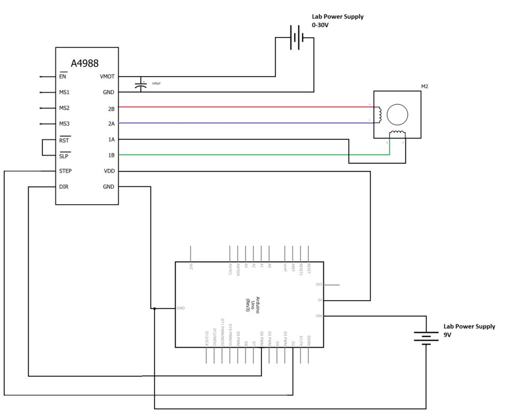
[Not the best schematic ever but it’s pretty simple. Note that what are shown as batteries are actually the two sides of my 30 Volt (max), 2 Amp bench power supply. Not quite the same thing, but my CAD doesn’t have a bench supply in its parts library.]
The VMOT and GND pin pair on the A4288 board were connected to the lab power supply, and the VDD and GND pin pair connected to the Arduino’s 5V output and GND pins. The other output of the lab PSU, set to about 7 volts, was connected to the Arduino’s VIN and ground pins. On the motor side of the driver module pins 1A/1B and 2A/2B were connected to the stepper motor. Finally, the STEP pin was connected to Arduino digital pin 2 and the DIR pin to Arduino digital pin 6. That’s it, although some explanation might be needed to get the motor connections right …
Motor Connections
It’s important that the 1A/1B outputs from the driver board are connected to the same phase in the motor. Same applies to the 2A/2B outputs. If the stepper motor has an instruction sheet all should be easy. If not, you need to identify which wires connect to which phase.
One way to do this is to connect two wires together and see if the motor shaft is more difficult to turn by hand – if it is you’ve identified the connections for that phase. Using this method I found that with my NEMA 17 one phase is red/blue and the other green/black. This was exactly the way the instruction sheet said it should be, which was good news.
Arduino Code
If you haven’t programmed an Arduino before it might be worth taknig a look at this post. The following is a very simple Arduino sketch that gets the motor to step. Movement is controlled by two Arduino output pins. Arduino pin D2 is connected to the A4988 STEP input and actually makes the steps happen. Arduino pin D6 is connected to the A4988 DIR pin and sets the direction in which the motor will step. The sketch steps the motor round a full revolution, reverses the direction and steps it back (at twice the speed) to where it started, then waits a second and does it all again:
#define STEP_Pin 2
#define DIR_Pin 6

void setup() {
  pinMode(STEP_Pin,OUTPUT);
  pinMode(DIR_Pin,OUTPUT);
}

void loop() {
  digitalWrite(DIR_Pin,HIGH);         // Set the motor direction
  // 200 pulses for one full rotation
  for(int x = 0; x < 200; x++) {
    digitalWrite(STEP_Pin,HIGH);
    delayMicroseconds(1000);          // 1ms pulse
    digitalWrite(STEP_Pin,LOW);
    delayMicroseconds(4900);          // 4.9ms between pulses - 1 second for full revolution
  }

  digitalWrite(DIR_Pin,LOW);          // Change motor direction
  // 200 pulses to get back where we started
  for(int x = 0; x < 200; x++) {
    digitalWrite(STEP_Pin,HIGH);
    delayMicroseconds(1000);          // 1ms pulse
    digitalWrite(STEP_Pin,LOW);
    delayMicroseconds(2400);          // 2.4ms between pulses - 0.5 second for full revolution
  }

  delay(1000);                        // wait one second before starting again
}
The result is shown in this short and not particularly exciting video:
Test Setup 2: NEMA 17 Motor with EasyDriver 4.4
I thought that since I my test setup was working it would be worth trying the other type of driver. The schematic for this test setup is very similar to the first:
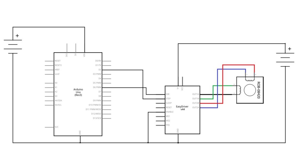
I used exacly the same Arduino sketch as with the A4988 driver, this time the arc covered by the motor was only 45°. This is because the default microstep setting with the EasyDriver is one eighth. A full revolution can be obtained by either pulling down driver pins MS1 and MS2 to give full step operation, or by increasing the number of steps to 1600 in the two for-loops in the sketch.
This is the motor running in eighth step with the unmodified Arduino sketch:
And again running the unmodified sketch, but this time with the MS1 and MS2 pins pulled low to give full step operation:
Conclusion
So that’s the absolute basics of getting a bipolar stepper working with the A4988 and EasyDriver modules. When one of these gets built into a project there are a few other tweaks that need to be made. Possibly the most important of them is getting the current limiting set on the driver to ensure the motor doesn’t get stressed. This wasn’t an issue for these quick tests, especially as I was running the drivers with an input voltage of about 9V (pretty close to their minimum).
There are additional input pins on the drivers that can be controlled by the Arduino rather than being hard wired with pull ups and pull downs. The most obvious of these are the microstep inputs, which would allow the step size to be varied under the Arduino’s control.
Both drivers have a sleep input, which puts the driver into sleep mode to reduce power consumption. They also have an enable input which could be used to implement an emergency stop.
I’ll be going in to these in more detail when I write up the stepper motor based project that’s currently under development.
One thought on “How to Use Arduinos to Drive Stepper Motors”