I’ve been quite focused on light building projects recently, but before I move on to other targets for my enthusiam I felt I had to make something with one of the Nichia COB LEDs I bought last year.
The Nichia chips have a power rating of 37 watts, a quoted CRI of 95+ and what appears to be a fairly serious level of light output. All very good, but the thing that held me back from building a project with one was the supply voltage requirement: 35 Volts. That’s potentially quite difficult to provide as it either needs a fairly big step up from a battery or other low voltage power source, or a high voltage source to use with a step down driver. The LED also needs a decent sized heat sink, possibly with a fan, to keep it running cool. None of these challenges was insurmountable, however, so this build started out as one possible solution for turning a Nichia COB LED into a compact studio monolight.
At least that was the intention before I fried my only spare Nichia chip in a tragic (for the LED) over-voltage incident, then found I couldn’t get a direct replacement. However, after a bit of searching I managed to find the Bridgelux BXRE-50S4001-C-73, which has a 40.2W power rating, needs a supply voltage of 34.4 Volts and has a CRI of 95: so is quite similar to the Nichia chip. This became the new light source for the project.
Parts
- Bridgelux BXRE-50S4001-C-73 COB LED chip
- HW-449 constant current boost LED driver
- PWM controller module
- Round CPU heatsink
- Thermal paste
- 50 mm cooler fan (12 volt)
- Fan on/off switch
- Universal to Bowens mount adapter
- Power switch
- Power socket
- Fuse holder
- LED (power indicator)
- M8 brass heat set threaded insert
- M3 brass heat set threaded insert (x4)
- Case – 3D printed (inevitably)
- 55mm M8 coach bolt
- 25mm M8 flanged hex bolt (or preferably 20mm if you can get them)
- M8 square hole construction washer (x2)
- M8 hex nut
- M3 bolt (x4)
- 10mm M5 round headed bolt (x3)
- Copper strip board (not much)
- 7812 voltage regulator
- Capacitors: 100nF and 470nF
- Resistor: 1kΩ
- 25mm and 15mm alloy strip, or equivalent
Electronics
The LED driver for this project is a HW-449 constant current step-up module. These modules can nominally take an input of 8.5 – 48 volts and step it up to 10 – 50 volts, with a 10A output drive capability. The Bridgelux LED chip has a power rating of 40.2W, so that’s about 1.2A at its 34.4V working voltage, which shouldn’t be a problem for the driver. The HW-449 has two variable resistors: the inner one sets the output voltage and the outer one sets the current – before assembly the voltage resistor was set to give an output of 34.4 volts with the module powered from the same type of Dell laptop supply that was used for my light panel project.
While the HW-449 module can give a stepped up voltage to drive the LED with a constant current, what it doesn’t do is give the capability to dim the LED. There are a few ways to do this, but probably the best is to use pulse width modulation. Doing PWM dimming basically requires an oscillator with a variable duty cycle (pulse width) driving a high power transistor circuit to switch the output of the LED driver – this can be done with a 555 timer, op amp comparator and a couple of stages of transistors to do the switching. Not too difficult to design, but as somebody who has very little spare time and has a tendency towards laziness, it’s a lot easier and quicker to buy in a module to do the job. The one I used is a Walfront PWM motor speed controller that can drive 450W, so should be well able to cope with a 40W LED.
The laptop power supply used for this project has an output voltage of 19.5V and as well as being stepped up to drive the COB LED chip, its voltage had to be reduced to drive the 12V fan. To do this I used just about the simplest circuit possible – a 7812 voltage regulator in tandem with a pair of capacitors. As well as powering the fan the 12V output, with a series resistor, was used to drive a power-on indicator LED – the circuit diagram for reglulator and LED is shown below:

Enclosure
The enclosure design was intended to be very simple, but it did grow arms and legs as I went through it. The original idea was to make a two-part housing to hold a Bowens mount adapter and the LED/heatsink, then bolt a stand mount, like the one I used for my light panel, on the bottom. Simple! Once I’d designed the first parts, however, it struck me that it would be good to design a stand mount that could also be used for hand-holding the light, so that was another two parts. Finally, with those designed, to finish the light I needed a lever to lock the angle of the head, and a locking wheel for the stand mount: these each consist of two parts: the tilt lever has a screw in back part to hold the captive nut in place and the stand mount has an insert in the top (just a cosmetic feature). So two parts had very rapidly become eight, but I think the result justified the extra effort. The image below shows what they look like in Fusion 360 (colours are Fusion’s choice rather than mine) and the STL files can be downloaded here.

Heatsink Assembly
With my chosen heatsink (i.e. the only round one in my box of spare heatsinks) the first step was a bit of hacksaw work: apart from the nice round fins, mine had four extrusions sticking out with through-bolts to attach to the processor socket, and another four extrusions for the fan to bolt on to. I removed the fan, then sawed off all the extrusions with a hacksaw, tidying up the results with a needle file.
To mount the heatsink and the two electronics modules inside the enclosure I assembled a framework from alloy strip. My workshop isn’t exectly set up for metal bending so it’s a bit rough and ready but it does the job – it’s basically a flattened U-shaped bracket bent up from 25mm strip that bolts onto the back of the heatsink, with a couple of cross bars made from thinner strip to mount the boards. All the holes for fixing the frame together and mounting the modules were tapped to avoid having to mess around with nuts when I was putting it together. Two additional holes were drilled in each of the side arms of the frame to line up with the holes in the top and bottom of the light body. These were once again tapped with a M2.5 thread.
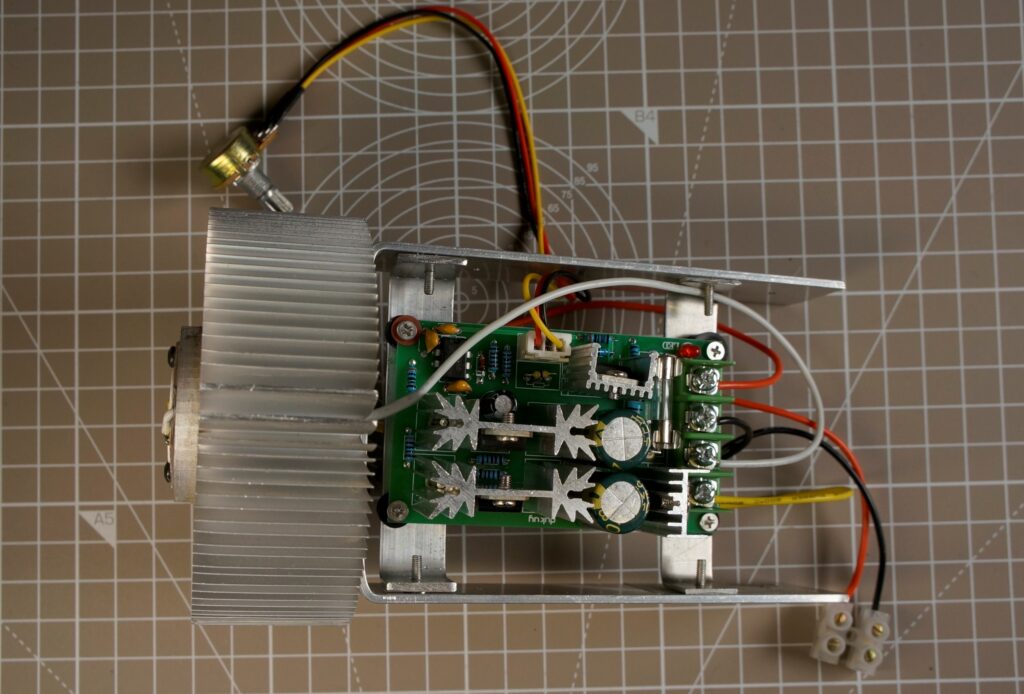
To mount the LED on the heatsink M2.5 holes were drilled and tapped in the front face of the heatsink, and a further two holes drilled right through the heatsink for the power wires. The LED had its back coated with thermal paste and was bolted to the heatsink using short M2.5 bolts. The power wires were then passed through the heatsink and soldered the the pads on the LED, with the other ends connected to the output of the PWM controller board mounted behind. The finished frame with modules mounted looks like this:

And from the PWM controller side:
The voltage regulator circuit was assembled on a small piece of strip board with a series resistor for the power LED, which was mounted on the back of the strip board.
Enclosure Printing and Assembly
For strength the handle mount, handle, tilt lever and locking wheel were all printed using PETG – in this case black 3D Warhorse PETG filament. The light’s body and end cap were printed with black Technology Outlet PLA, while the inserts for the tilt handle and stand locking wheel are Technology Outlet white PLA.
The end cap was printed hollow end down with sparse support to prevent warping. It took a few minutes to dig all of the support material out of the completed print, but the end panel is square and warp-free. The body was printed wide end down with supports – this is the light’s largest component and took about a 22-hours to print on my Creality Ender 5 Pro.
Once the parts were printed there was a small amount of assembly to do. Starting with the easiest: an M8 nut was inserted into the tilt handle’s body (no glue needed) and the insert was carefully screwed in on top of it to keep in in place.
The M8 flanged bolt was cut down by about 5mm (I couldn’t source 20mm flanged bolts, so had to buy 25mm ones which are a little longer than I wanted) then glued into the stand locking wheel using the ubiquitous five minute epoxy. While the epoxy glue was out, the insert was glued into the recess on top – this only needed a tiny amount of glue as the insert pretty much clicked into place. The result is a reasonably authentic looking light-stand mount locking wheel.
To prepare the front of the light body, the rubber liner was removed from the inside of the Bowens mount adapter and the mount fixed into place using three 10mm M5 round headed bolts – in the print the three holes for fixing the mount are countersunk, but mine didn’t line up perferctly so had to be drilled out slightly. I’m guessing the spacing of the inserts on my Bowens adapter wasn’t exact, as using the pattern function in Fusion to position the holes, the print is almost certainly spot on.
Next a soldering iron was used to fix an M8 heat set threaded insert into the hole at the bottom of the handle, and four M3 heat set inserts were fixed into the holes (in a rectangle pattern) on the bottom of the light body.
With all the heat set inserts in place the handle mount was bolted to the light body using four M3 bolts. The handle was then attached to the mount using the coach bolt, with a square hole washer on either side and the tilt lever screwed on. Finally the locking wheen was screwed into the M8 insert at the bottom of the handle.
Putting it all together
Starting with the lamp’s end cap, the power socket, fuseholder and fan were fitted in place and wired up: power positive to fuse holder, other side of the fuse holder to a flying lead; power negative to the fan negative and another flying lead; fan positive to a third (lighter gauge) flying lead.
The power LED was fitted in the hole in the side of the light body and the the board hot glued in place. With that done there was just a bit of internal wiring to do and the light could be tested. At this stage I didn’t hard wire the power switch, as it had to be inserted into its hole in the side panel from the outside, and I still had to work out the scale for the intensity control and make the label for the panel.
After testing with my Lux meter to find the half, quarter and eighth light intensity settings for the potentiometer, an insert for the side of the light was drawn up and printed on some sheen effect paper I had lying around. This was sealed with a couple of coats of artists varnish, then cut down to size and the holes cut out. The finished piece was then stuck to the side of the lamp body, and the power switch and knob for the intensity control added. The flying leads in the cap were then connected up to the electronics in the body and the cap screwed into place. Done!

Powering the lamp up, it appeared pretty bright and controllable. The heatsink does get quite warm and my main worry with the lamp is heat dissipation. However, having run it for several sessions with the temperature probe from my multimeter stuck in the vents at the top/front of the light, I haven’t yet measured any temperatures that are alarming. That said, I do tend to run with the fan on when the light is working at full power.
And finally, the reason for fitting that Bowens adapter at the front – the ability to fit light modifiers. Below is the light with a standard 18cm reflector: unfortunately all my Bowens fit standard reflectors are grey, but otherwise they look like they were made for each other.

2 thoughts on “DIY High Power LED Monolight”