The Prototype
Taking a (semi) objective look at this site recently I realised that it’s ages since I built a project with an Arduino. That’s certainly not because I’ve built everything I can think of that uses one. In fact there are quite a few projects on my long-term list that need a microcontroller. So it’s time to take something off the list and actually build it. First up, a motorized macro rail for focus stacking.
Those not familar with macro photography may ask “why?” Well, it’s all about depth of field – working with macro lens setups you don’t get much. That means you generally have to pick which part of the subject you want to be in focus and the rest won’t be. But there is another way. It goes something like this:
With the camera mounted on a macro rail, you focus on the nearest part of the subject and take a shot. Then without changing the focus you move the camera forward a tiny amount and take another shot. Then you move the camera forward another tiny amount and take another shot. Basically you keep repeating this process until the whole subject has been photographed. You then load the images into photo-stacking software and combine them using the in-focus parts of each shot. Out the other end comes a shot that’s sharp from front to back. Magic!
The trouble with this is that actually doing the shot-taking part is very boring. So as your mind drifts, half way down the stack you potentially get the move interval wrong or miss a shot. Even if you don’t, it’s a very slow and tedious business. If only there was a way to make it a bit less boring …
The Motorized Macro Rail
An obvious improvement would be to get a machine to do the repetitive mechanical part of the focus stacking process rather than a short-attention-spanned human. Sounds like an ideal job for an Arduino.
The new process becomes:
- Set the start point of the stacking run,
- Focus the lens on the front of the subject,
- Set the end point of the stacking run,
- Enter the inter-photo distance,
- Watch the macro rail step through the macro run,
- Download the photos and process them.
This sounds simple enough, as these projects always do at the start. Digging into what’s needed in a bit more depth, there’s effectively a regular macro rail, but rather than being hand cranked it’s driven by a stepper motor. Control of the stepper is handled by an Arduino, which also drives a display, has some input buttons and triggers the camera and flash. Most of that’s pretty familiar stuff, but I did have to do some background research to work out how to control the stepper with an Arduino.
Having done a few Arduino developments in my time I knew that this project was going to take a while to complete. As a result I’ve split the write-up into three parts. This first part is all about getting a physical prototype macro rail built and working, to the extent that the camera could be moved backwards and forwards using a couple of test sofware routines. The second part will cover modifications to the prototype to make a production version. The final part will decribe the electronics and development of the “proper” software to run it all.
The Rail
I thought about using a commercially available manual macro rail as the basis of this build. It would need to be something with a decent quality lead screw, like this Haoge FM-160 or this Nisi NM-180, so not the cheapest of units. However, I was a bit concerned about whether I’d be able to get a coupling on one of these to drive it with with a motor.
As a result I decided to make my own. That gave me a lot more control over access to the lead screw and attaching the motor. It also made it easier to incorporate electronics, display, control buttons and battery. The downside, of course, is that it took much longer to design and put together.
The basics of the rail are simple enough: a pair of end blocks with a moving platform between them. The platform runs on a couple of rails and is moved by a lead screw. Blocks and platform could be made from just about anything that’s drillable – wood being a common choice for DIY’ers. In an ideal world I’d machine them up out of alloy, but since I don’t have a milling machine (at least for now!) I decided to 3D print them.
Lead Screws
When buying a lead screw there are a couple of important considerations: thread pitch and lead. Pitch is the distance between screw threads and lead is the linear distance travelled by the nut for one revolution of the screw. For a single start screw the lead will be equal to the pitch. With multi-start screws lead is the pitch multiplied by the number of starts.
For this application I wanted to keep the lead small, so went for a single start lead screw with a pitch of 2mm. This gave me a movement of 2mm per revolution, or 10 microns per step using a NEMA 17 motor. That’s not a bad start, but throwing the stepper driver’s microstepping capability into the mix the steps really get quite small. Using a A4988 driver set to 1/16th step this gives a minimum step size of 0.625 microns. I think that should be good enough for this application.
Design
End Blocks
The rail has a fixed block at each end, with a movable platform between that’s driven by the lead screw. To keep it properly supported, the platform runs on a stainless steel shaft on either side.
The front end block has mounting holes for the NEMA 17 motor and a big hole for the flexible coupling on the motor shaft. It also has a pair of holes with side grub screws for attaching the 7mm diameter shafts at the sides.
The other block (back block) fits an 8mm vertical lead screw bearing to support the far end of the lead screw. It also has holes with grub screws for securing the side shafts. For the back block there’s also a separate rectangular piece with bolt holes that drops in above the lead screw bearing to make it look a bit neater.
Platform
The platform runs on the pair of 7mm shafts and has oil filled sintered bronze bushes to ensure it moves smoothly. The lead screw runs through the middle of the platform with a lead screw nut attached to the platform at the motor end to turn the screw’s rotation into linear motion.
The platform is split hoizontally into two parts to make it possible to print and to insert the bushes.
First Print
The first prototype print of the two end blocks and the platform was just made to see how it was all going to hang together and make sure it actually worked. For this prototype I used a pair of square bars at the bottom to support the end blocks. Since the 3D printed parts were all throw-away prototypes they were printed in eSun (bright) green PETG. This filament was bought for a very specific project and strangely enough I haven’t managed to find a use for it since.
The two end blocks with platform, lead screw and motor are shown below:
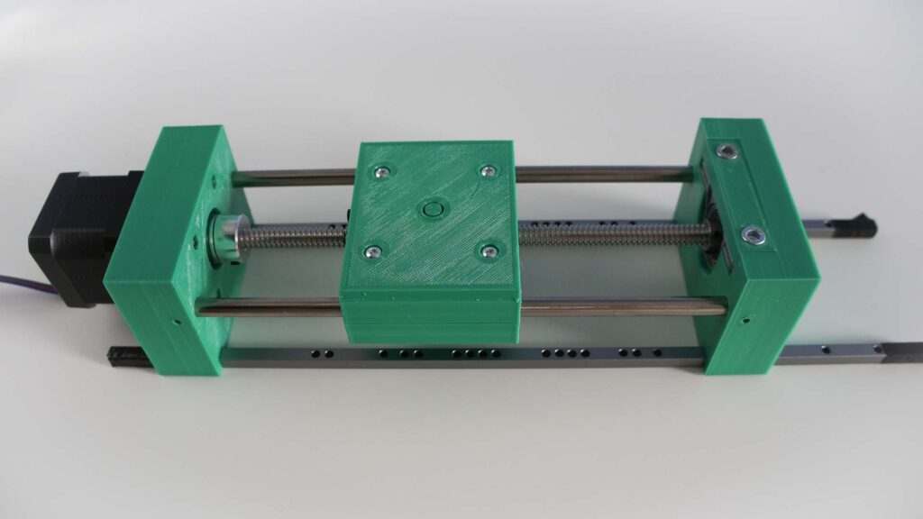
… and a short video of the green monstrosity doing what it’s meant to do:
For this test the code used in my earlier Arduino/stepper motor investigation was used, with the number of steps increased to 3000. The driver board was set to full step giving 15 full rotations of the motor shaft. With my 2mm pitch single start lead screw this gives a horizontal movement of 3cm.
Next Steps
While this first prototype shows that the basic concept works, there are a few modifications and enhancements that need to be made before I make a final version of the rail:
- The rail needs a proper base instead of the square bars. The base should have a tripod mount screw.
- My lead screw is slightly long for the pair of recycled side shafts. I could fix this by sourcing a longer pair of 7mm shafts. However, a more flexible solution would to make a hole in the back block so the end of the lead screw doesn’t have to be exactly the right length for the shafts.
- The top of the platform needs to be higher, as the release screw for the Arca Swiss plate has to clear the front block (I never thought about that when I visualised the design). Alternatively I could mount a ball and socket head on the platform. This would need a change to the mounting arrangement, which in this prototype was going to be a heat set 1/4 20 threaded insert.
- I decided to switch from using a vertical lead screw bearing at the back end block to a flat front-mounting one. This should make the finish of the back end block neater and will allow its height to be reduced.
- I want to incorporate a limit switch at each end to provide an emergency stop if the platform gets too close to the end blocks.
These mods will be documented in the second part of the write-up. At that point a finalised parts list will be included, along with the stereo lithography files for the printed parts.
4 thoughts on “Building a Motorized Macro Rail”
Looks an interesting project! Combining photography, programming, electronics and 3D printing!
I’ll certainly be following this with interest!