Picking up from where part 1 of the Motorized Macro Rail project left off:
Design Modifications
I’ve made few improvements to the prototype design for the “production” version, as outlined at the end of part one.
The first of these is that the square bars at the base of the prototype have been replaced by a 3D printed base plate. This bolts to the two end pieces to provide a solid frame for the mechanism. The length of the base has been shrunk down slightly so that it fits better (diagonally) on the build plate of my Ender 5 printer. The plate has a pair of tripod mounts on the bottom and also has a wiring channel on the top with a separate cover for mounting the limit switches.
The next improvement was to add limit switches at either end. These are a safety feature that should stop the platform driving into the end block or motor coupling if something goes wrong with the software. The actual switch units I’m using are very small ones that were salvaged from a Canon Pixma TS8251 printer. Switches exactly like these may not be generally available, but there are plenty of suitable alternatives on Amazon and eBay, amongst other places.
Front and End Blocks
Moving on to the end block, this now has a hole to allow the lead screw to protrude. The benefit is that the lead screw doesn’t now have to be an exact match to the length of the base. The end mount has also had a redsign around the lead screw bearing, to fit a horizontal rather than vertical type. This looks neater and shaves a few millimetres off the height of the block.
The front block is pretty similar to the first prototype. The only real changes (apart from the new base) are four mounting holes for the motor cover and a small hole in line with the wiring channel. The latter allows the wires from the limit switches to pass though the block.
Platform
The underside of the bottom part of the platform has been slimmed down at the edges to allow clearance for the limit switches. Otherwise it’s the same as the earlier prototype.
The upper part has been extended upwards by 20mm and tapered towards the top. I did consider using a ball and socket head on top of the original platform, but decided against this due to the (excessive) extra height and weight it would add. I thought this might affect the balance and stability of the rail. The top now has an 8mm heat set insert for attaching the Arca-Swiss type plate using a coutersunk M8 bolt. The tightening knob on the Arca plate now clears the front block, and a macro lens on the camera is well clear of the top of the end block.
And finally, an additional part:
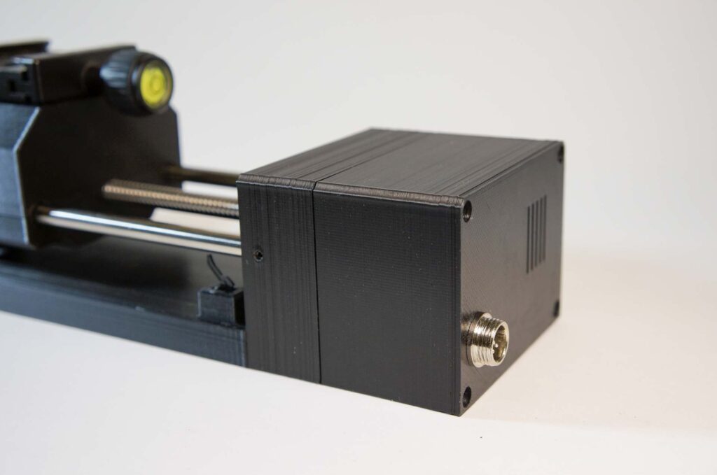
Motor Cover
The NEMA 17 stepper motor is a handsome looking beast, if you’re into looking at motors. For those of us who aren’t I made a cover to hide it. This has the added benefit that it protects the motor’s plug and leads, and has a socket for connecting the box containing the control electronics. The cover bolts on to the outside of the front block using four 30mm (thread length) M3 cap screws.
Printing and Putting it Together
Printing
I printed all the parts with Copymaster 3D Deep Black PLA filament with a layer thickness of 0.2mm (standard quailty). Print temperature was 210°C and build plate temperature 50°C. I would have preferred to print using PETG for extra strength, but haven’t yet managed to find a black PETG filament that doesn’t print a bit shiny. Any suggestions, please leave in the comments.
All holes were designed slightly oversize to allow for shrinkage during printing. After printing they were all cleaned out with the correct size drill. Threaded holes were modelled in design, but I carefully re-tapped the ones that had been printed vertically to ensure the bolts went in cleanly. All bolt/grub screw holes are M3 thread with the exception of the two for the lead screw bearing, which are M4.
Assembly
The steps to put the main printed parts together were:
- The heat set inserts (8mm on the platform top and 1/4″ 20 tpi on the bottom of the base) were heated with a soldering iron and pushed into place.
- The shaft coupling was attached to the stepper motor shaft using its grub screws, then the stepper motor was bolted to the front block using four 25mm (thread length) M3 cap screws.
- Front block was bolted to the base using two 12mm M3 cap screws.
- Lead screw bearing was bolted to the end block using two 16mm M4 cap screws.
- The bronze bushes were put in their recesses in the platform bottom and the platform top was attached with four 35mm M3 cap screws.
- Lead screw nut was bolted into the recess in the platform assembly using four 12mm M3 cap screws.
- Shafts were pushed into the holes in the front block and secured using two M3 grub screws.
- Lead screw and shafts were fed through the platform and and the lead screw attached to the motor coupling.
- The other end of the lead screw was fed through the lead screw bearing and the shafts pushed into the holes in the end block.
- End block was bolted to the base using a pair of 14mm M3 cap screws.
- Shafts in the end block were secured with two M3 grub screws.
- The grub screws in the lead screw bearing were tightened.
Unprinted Parts
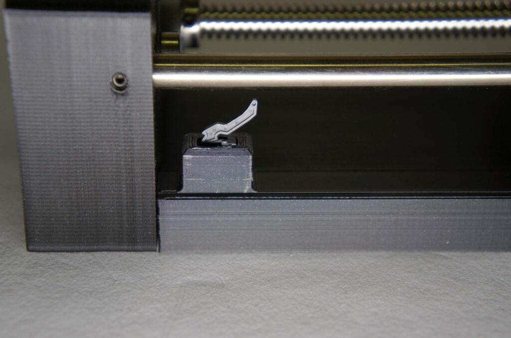
That was the basic unit assembled, but there was still some work to be done. First the limit switches had to be wired up and fixed in place in the wiring cover. My switches have a very small lug on either side, presumably for alignment. I filed a small slot in the sides of the holes in the wiring cover to accomodate these.
The switches are wired in parallel as they’re connected to the A4988’s enable input. I used 28 AWG silicone covered wire for the part that comes out to the connector to allow flexibilty when I’m trying to get the motor cover on. For the connection between the two switches I used much thinner wire, as there isn’t a lot of space to spare in the wiring channel.
With the switches wired up they were glued in place with a couple of spots of JB-Weld epoxy. The wiring cover was also glued in place using the same adhesive. This epoxy is slower-setting than my usual five minute stuff, but it dries blackish, so is less visible on black parts.
Control Box Connection
The limit switch wires were soldered to two pins of a GX12 6-pin socket. The other 4 pins of the socket were soldered to a short cable that plugged in to the stepper motor. The pinout I used for the socket was:
- Red Stepper
- Blue Stepper
- Black Stepper
- Green Stepper
- Limit switch
- Limit switch (GND)
The pin order isn’t important as long as it’s consistent between the macro rail and the controller. When the socket was soldered up I secured it in its hole in the motor cover.
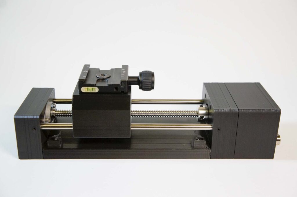
I then bolted the cover to the rail’s front block using four 30mm M3 cap screws. Finally I bolted an Arca-Swiss type plate to the top of the platform with a 16mm M8 countersunk bolt. The assembled unit looks like this:
Parts List (excluding control box)
- NEMA 17 stepper motor
- Lead screw: 8mm diameter, 2mm pitch, single start
- Lead screw nut
- 5mm to 8mm shaft coupling
- Horizontal 8mm lead screw bearing
- Pair of stainless steel shafts (7mm diameter)*
- Sintered bronze bushes, 7mm internal diameter (x4)
- Limit switch (x2)
- M8 heat set insert
- 1/4″ 20 heat set insert (x2)
- 6-pin GX12 socket
- Copymaster 3D deep black PLA filament
- M3 and M4 cap screws
- M3 set screws (grub screws)
- 16mm M8 countersunk bolt
- Arca-Swiss type plate
*My steel shafts started life as a single 408mm shaft that I recovered when I stripped down an old scanner. I hacksawed it in half and dressed the ends with a file to give me the two ~200mm shafts needed for this project.
A zip archive containing .stl files for the seven printed parts needed to build the macro rail can be downloaded here.
Control Electronics
After all the fun and games I had with the print layer shift problem – described here if anyone’s interested – I haven’t yet been able to get started on the controller. As a result the list of parts I need for the control box isn’t 100% clear. I know that in order to reduce the footprint of the electronics I’m planning to use an Arduino Nano. The stepper motor driver will be an A4988 as it can do 1/16th step, and the display is likely to be a ST7735 1.8″ colour TFT unless I hit a major snag with it. The complete parts list for the control box will be in the final part of this project writeup.
To test the rail in the meantime I used the Arduino and stepper driver setup and code I used in my post about controlling steppers using Arduinos. All looks good so far.
One thought on “Building a Motorized Macro Rail: Part 2”