In earlier Arduino based projects I’ve used two different monochrome LCD screens, but these were quite limited in their display capabilities. In the drop controller I went with the two line by 16 character LCD Keypad shield. This was very easy to integrate into the build physically, but did lack a little finesse. In the slightly more recent photogate trigger I used the Nokia 5110 display. This has a resolution of 84 by 48 pixels and it can display more lines of text, or even rudimentary monochrome graphics.
For my macro rail project I decided to up the ante and go for a colour screen, namely the 1.8″ ST7735 TFT display. This can display 160 by 128 pixels with 16-bit “High color” and can draw shapes as well as text. It also has an SD card socket on the back, although I’m not going to use this at present.
The screen has a height of just over 3.5cm and a width of about 3cm. To me this raised the possibility of having four or five PCB mounted pushbutton switches up the side, aligned with text on the screen for menu item selection. I’m planning to control the macro rail with an Arduino Nano, so this time I’ve done my test setup with a Nano rather than the obligatory Uno.
Getting Started
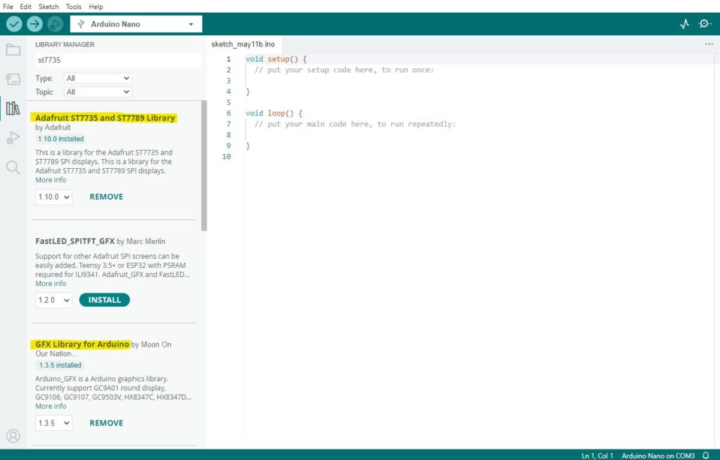
In order to control the ST7735 with an Arduino there are a couple of libraries I had to add to the Arduino IDE: Adafruit ST7735 and Adafruit_GFX. These were added to the IDE via Tools>>Manage Libraries… With the libraries installed, a quick IDE restart had me ready to go:
Hardware Connection
The next step was to connect the screen to the Arduino Nano: this only required five wires plus power. However, it’s worth noting that my test ST7735 is a 3.3 Volt unit. While the Nano can provide 3.3V power, the digital output pins are 5V. To protect the display I used 1KΩ resistors in series with the five Arduino data lines.
To make life very easy, the 7735 uses the SPI (serial peripheral interface) protocol to communicate with the Arduino. With Arduino, SPI can either be implemented in hardware or software. I decided to use the hardware option as it’s faster than software SPI, but has to use the board’s hardware SPI pins. For the Nano these are Pin 11 for MOSI and Pin 13 for SCLK. With software SPI it’s possible to assign your own pins, but unless there’s a particular need to use D11 and D13 for something else, I’m not sure I can see any benefit.
The full set of connections from Nano to ST7735 is:
| Arduino Nano | ST7735 TFT |
| 3.3V | Vcc |
| GND | GND |
| D11 | SDA |
| D13 | SCL |
| D5 | RES |
| D6 | CS |
| D7 | DC |
Pretty straightforward stuff: I wired mine up on a small breadboard to get me started quickly.
First Test
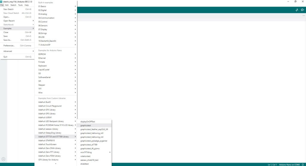
With the display connected to the Nano I needed a sketch to check that the display was actually working. Luckily Adafruit have provided a couple of useful ones that can be accessed in the IDE via File>>Examples>>Adafruit ST7735 and ST7789 Library. The best of these was called “graphicstest”:
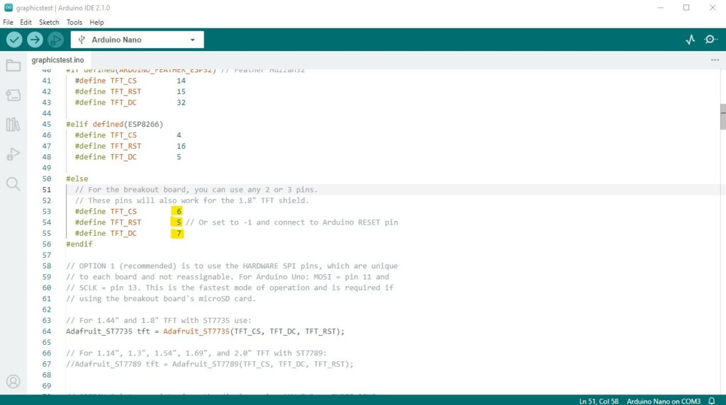
This pretty much does what it says on the tin, once a very minor mod has been made to it. Because I was using D5, D6 and D7 for RES, CS and DC respectively, these had to be reflected in the define statements (highlighted) at the start of the sketch:
With the define statements fixed, I compiled the sketch and uploaded it to the Nano. When the upload was complete the display ran through its range of text and graphical displays, proving that the screen was working and the interface to the Nano was good.
Programming
One of the great things about the graphicstest sketch is that it displays text and various graphics, so gives a quick insight into how to do these yourself. It also gives you bits you can pick out and tweak to help work out how to implement the displays you actually want.
Displaying Text
Displaying basic text is easy, but requires a few function calls to set things up prior to actually printing the text. First, set the text size using the following function:
void setTextSize(uint8_t size);
where size is an 8-bit integer. As far as the available text sizes are concerned, text size 1 is small, size 2 quite big and anything higher is, in my view, too big for the screen. Half sizes would have been useful, as between 1 and 2 would probably be ideal for what I was trying to do. However, we can only work with what we have!
I believe it may be possible to do intermediate text sizes with a different ST7735 library, but that’s another rabbit hole to chase down some other time.
Text colour is set with another call, this time passing an unsigned 16-bit integer:
void setTextColor(uint16_t color);
Colours can either be pre-defined values like “ST77XX_GREEN” or 16-bit hex values such as “0xEC02”.
It is possible to just print lines of text to the screen, but to fromat it neatly the position of each string can be set using the following function:
void setCursor(int16_t x0, int16_t y0);
where x0 and y0 are the coordinates of the top left of the first character, passed as unsigned 16-bit integers. [(0,0) is the top left corner of the screen.]
With the text parameters set up, the actual text is just written tft.print() instructions , which work the same as print() in serial printing.
Displaying Symbols
The GFX library implements a range of primitives: points, lines, rectangles, triangles, circles and rounded rectangles. For the display I was aiming to implement I only needed a few of these, detailed below.
As the screen area is quite small I decided to make my status symbols a traffic light system. This removes the need to make very small ticks and crosses – instead just having to use filled circles. Very usefully, filled circles have been implemented in the library and just require four parameters to be passed to the function:
void fillCircle(uint16_t x0, uint16_t y0, uint16_t r, uint16_t color);
where the parameters, all passed as unsigned 16-bit integers, are:
- x0 and y0 are the position of the centre of the circle,
- radius is the radius of the circle in pixels,
- color is the circle’s colour: either pre-defined or a hex value (same as text colours, above).
There’s another library function to draw unfilled circles, which could be useful highlighting list items for selection. Calling it uses the same parameters as the filled circle:
void drawCircle(uint16_t x0, uint16_t y0, uint16_t r, uint16_t color);
Finally, for highlighting text items on the menu there’s a rounded rectangle:
void drawRoundRect(uint16_t x0, uint16_t y0, uint16_t w, uint16_t h, uint16_t radius, uint16_t color);
This one has a few more parameters:
- x0 and y0 are the coordinates of the top-left corner,
- w and h are the width and height of the rectangle,
- radius is the radius of the corner rounding in pixels,
- color is the colour.
Again all parameters are passed as unsigned 16-bit integers.
Test Sketch
Looking forward to the elements I think I need to produce the UI for the macro rail, I designed a simple display with a heading, a list of menu items on the left and values and status indicators on the right. I added highlighting outlines to one each of the values and status indicators. I coded this as a simple static display page, using a subset of the GFX library’s functionality.
The display I produced is shown here:
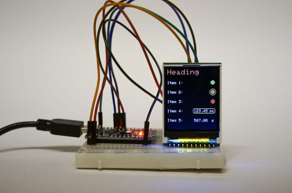
… and the sketch to create it is listed below:
#include <Adafruit_GFX.h>    // Core graphics library
#include <Adafruit_ST7735.h> // Hardware-specific library for ST7735
#include <SPI.h>

#define TFT_CS         6  // define CS, RST and DC pins
#define TFT_RST        5
#define TFT_DC         7

Adafruit_ST7735 tft = Adafruit_ST7735(TFT_CS, TFT_DC, TFT_RST);

void setup() {
  Serial.begin(9600);
  tft.initR(INITR_BLACKTAB);      // Init ST7735S chip, black tab
  tft.setTextWrap(false);
  delay(500);
  tft.fillScreen(ST77XX_BLACK);   //clear the screen
}

void loop() {
  // write the heading
  tft.setCursor(0, 0);
  tft.setTextColor(0xE383);
  tft.setTextSize(2);
  tft.print("Heading");
  // write the menu items
  tft.setCursor(0, 32);
  tft.setTextColor(ST77XX_WHITE);
  tft.setTextSize(1);
  tft.print("Item 1:");
  tft.setCursor(0, 57);
  tft.print("Item 2:");
  tft.setCursor(0, 82);
  tft.print("Item 3:");
  tft.setCursor(0, 107);
  tft.print("Item 4:");
  tft.setCursor(0, 132);
  tft.print("Item 5:");
  // write some filled circles
  tft.fillCircle(118, 35, 5, 0x1F09);   // green
  tft.fillCircle(118, 60, 5, 0xED42);   // orange
  tft.fillCircle(118, 85, 5, 0xF8E0);   // red
  // write two values as text
  tft.setCursor(70, 107);
  tft.print(123.45);
  tft.setCursor(70, 132);
  tft.print(567.8);
  // write indiviual characters
  tft.drawChar(110,107,0xE5 ,ST77XX_WHITE, 0, 1);
  tft.drawChar(116,107,0x6D ,ST77XX_WHITE, 0, 1);
  tft.drawChar(116, 132,0x73,ST77XX_WHITE, 0, 1);
  // highlight second circle
  tft.drawCircle(118, 60, 8, ST77XX_YELLOW);
  // highlight first value
  tft.drawRoundRect(67, 104, 58, 13, 4, ST77XX_YELLOW);
}
Note: the above is purely a test sketch with a lot of static values and positioning, but it shows what the screen can do. Things will get more complicated code-wise when this gets turned into a properly structured sketch and integrated into the macro rail.