I’ve recently spent a chunk of time cleaning up and shooting with my growing collection of Helios 44 lenses. As a Canon shooter, one potentially nasty issue with these lenses is that the mirror on a full frame DSLR can apparently hit the protruding rear lens element at infinity focus. This is an issue that’s been reported with some versions of the Helios 44 with some Canon full frame DSLRs.
Taking a few measurements on my 44’s, the rear element appears to protrude through the M42 to EF adapter by about 1.4mm at infinity focus on all of them. So it looks like any one of them could potentially cause the mirror problem on the right (or wrong) DSLR body. What I don’t know is if my 6D is one of the Canon models that might be an issue.
As a result, being a bit risk averse when it comes to taking chances with my cameras I’ve never tried any of my Helios 44s at infinity focus on the 6D.
However, last year I upgraded my camera and now mainly use a Canon EOS R, with the standard Canon RF to EF mount adapter to use my EF lenses. Because of the reduced mount to sensor distance with the R-series cameras the adapter is quite thick and that extra distance allied to the lack of a mirror means it’s now safe to use the Helios 44s at any focus distance I want.
The Idea: a Rear Mount Flare Adapter
After I’d been playing with the 44s I also dug out my anamorfake modified Pentacon 50mm f1.8 and stuck that on the M42 mount on the front of my EF/RF adapter. This gave great elliptical bokeh, but also got me thinking: what about the anamorphic style flares I was working on a couple of years back? Going back to my experiments with flare filters post, possibly the best result was with the flare filter at the back of the lens. So inspired by the Canon RF-EF adapter with drop-in filters, how about making a mount with a slot-in flare filter?
Taking another sideways step, how about making an elliptical aperture insert for the adapter as well? I’ve no idea how well having the aperture behind the lens would work optically, but since it’s only likely to be a small change from the flare filter insert it’s got to be worth a try.
Parts
- Thin EOS RF to M42 mount ring (mine is Pixco brand bought on eBay)
- Flanged M42 (to Canon EF) mount ring
- 3D printer filament
- Fishing line (0.1mm/2lb)
- M1.6 bolts (5mm and 12mm)
- Heat set threaded inserts (M1.6 x 4mm)
- 52mm internal diameter, 1.5mm diameter o-rings (x2)
Adapter Design
Looking at the lens mount to sensor distances for the Canon EF and RF mounts, for the EF mount it is 44mm and for the RF it’s 20mm. That means the total thickness of the adapter should be 24mm. Measuring the thickness of my Canon EF-RF adapter reassuringly gave me a reading of 24mm.
I decided to use a pair of metal lens mounts at the ends for solidity. The one at the camera end is a thin M42 to RF mount that’s designed to be used with extension tubes. This has a thickness of 1.7mm, so the length of the adapter’s body has been set at 22.3mm to allow for this.
Lens End
At the lens end I’ve used a flanged M42 to Canon EF mount, as a) I had one lying around, and b) its overall diameter is similar to the M42-RF mount used at the other end of the adapter.
The thickness of the M42 to EF mount added to the 24mm depth of the adapter and the 20mm distance to the sensor in the EOS-R should give very close to the mount to sensor distance for M42, which is 45.46mm. The thickness of the ring should ideally be 1.46mm, but anything in the range of about 1.25 to 1.5mm should work. Using a flanged mount means that later ‘automatic’ only M42 lenses (like the Helios 44M-4, with the stop down push pin in the mount) can be used at all apertures.
Using different lens to EF mounts for the front of the adapter should be possible. Non-EF mounts may be problematic, however, as many of them have a smaller diameter than the Canon EF. If the chosen mount’s overall diameter is smaller it may not be possible to drill it so the fixing screws line up with the holes in the adapter.
Adapter Body and Internals
The adapter body is designed to be printed in two parts, split at the front of the side slot. This means the body can be printed without supports round the slot-in insert, which should make for a smoother surface and a better seal.
Taking a look at my Canon EF-RF adapter, the inside surface has a series of ‘baffles’ to reduce internal light reflections. Given that my adapter is designed for 3D printing, creating similar baffles in a single print would be very difficult.
As an alternative I’ve designed them as a series of rings that can be printed independently and stacked inside the back part of the body of the adapter before the two parts are screwed together.
To ensure a reasonably light- and dust-tight seal round the slot-in insert I’ve included a pair of o-rings, one on either side. One of these is in the front baffle and the other is in the back of the front body part.
The mounting rings at either end are designed to be held in place by M1.6 bolts, with heat set threaded inserts in the adapter body.
Filter Insert
The slot-in insert comes in two flavours. The flare version has a recessed hole in the centre to fit a disk holding the fishing line and the second has a fixed elliptical aperture in the centre.
Adapter Drilling Templates
It’s pretty important that the mounts at either end of the adapter are aligned properly. If the rear mount isn’t the slot in insert won’t be horizontal, which apart from looking rubbish would make it difficult to get the fishing line and elliptical aperture vertical. With the front mount, misalignment would mean the aperture markers and focus scale might not be in very usable positions. To ensure proper alignment I’ve designed a couple of printable drilling templates.
All adapter components were designed in Fusion 360. Including the drilling templates there are ten separate parts:
- Back body part
- Front body part
- Insert
- Flare ring
- Insert with aperture
- Back baffle
- Baffle ring 2
- Baffle ring 3
- Rear mount drilling template
- Front mount drilling template

The collection of components (in Fusion 360) is shown above and a zip file containing .stl files for them can be downloaded here.
Printing and Assembly
Printing
Several of the parts are designed to be printed with a 0.12mm layer height rather than the standard 0.2mm for my printer. The back body part, back baffle, baffle ring 2 and the two drilling templates can be printed with the standard 0.2mm layer height. The front body part, baffle ring 3, inserts and flare ring have to be sliced and printed with a 0.12mm layer height.
All parts were printed with Technology Outlet deep black PLA. This filament has a fairly matt finish, so is good where you don’t want too much light bouncing around. All parts were printed with a print head temperature of 210°C and build plate temperature of 50°C.
The body back part was printed mount end to the build plate with no supports. The front part of the body was printed front end (EF mount) to the build plate with supports – this ensured that the stepped edge that overlaps the back part of the body printed cleanly.
The drilling templates could have been printed with just about any available filament. I used the same Technology Outlet PLA as for the main parts as it was already loaded in my printer.
Adapter Assembly
Lens Mounts
The drilling templates snap on to the back of the lens mounts. The image below shows the templates on the mounts – M42/EF on the left (after drilling) and the M42/RF on the right (before drilling).
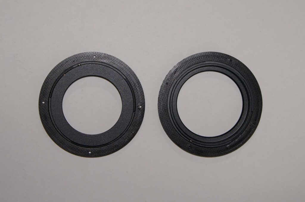
For the M42/EF mount the template has a little slot at the top and, looking from behind, the left hole should align with the locking slot on the mount. Three 1.6mm diameter holes were drilled using the other three holes in the template as guides. The three holes plus the centre of the locking slot were then countersunk on the front (lens side).

For the RF mount the slot in the template aligns so that it’s visible through the locking slot on the mount. For this one all four holes were drilled at 1.6mm. The template was then removed and the holes countersunk from the camera side. There’s not a lot of space between the protruding back of the mount and the holes, so countersinking was done by hand using a 3.5mm drill bit.
Beware: It’s very important that the countersinking is deep enough for the screw heads on the RF mount not to protrude at all. If they do they will foul the mount on the front of the camera and may damage it or jam when trying to remove the adapter. When fixing the M42/RF mount to the back of the adapter body, make sure the screw heads are better than flush before taking it anywhere near the camera mount!!
As the drilling and countersinking produce a fair bit of fine swarf and dust, both parts were washed in soapy water before assembly was started. The drilled and countersunk mounts are shown below:

Adapter Body
After printing the front body part the supports were removed from the inside. The surface this left was pretty uneven, so I smoothed it down using a Dremel with a small sanding disk attachment. After sanding, the front body was washed in soapy water as I really didn’t want any of the the plastic dust to get inside my camera.
Heat set inserts
The heat set inserts for this design are small, so they heat up and cool down very quickly compared to the larger inserts I’ve used previously. This means they can end up in the wrong place if you’re not very careful with them. I drilled out the first approximately 2mm of the insert holes with a 2.25mm drill so that the ends of the inserts could sit in the right position before I applied heat. They were heated with a fine-tipped soldering iron that was held absolutely vertical as they were pushed into the holes in the back- and front-body.
There are four inserts in the rear of the back adapter part for mounting the M42/EF mount, and three in the front of it, as shown below. These are for three of the screws that fix the lens mount to the front part of the adapter.

The final heat set insert is above the slot opening on the front of the adapter’s front body part:

Baffles and o-rings
Once the heat set inserts were fixed, the baffles were glued in place in the adapter’s back body part using a small amount of J-B Weld epoxy. The order they were added was: back baffle, baffle 2 then baffle 3. When number 3 was in place one of the o-rings was inserted in the groove around the outside.
The other o-ring was carefully inserted in the groove in the back of the front body part. Both o-rings needed a bit of ‘massage’ as they were inserted as they tend to stretch, giving the impression they are too big for the slots. When they are in place they look like this:

Putting it together
At this point the adapter body was ready to put together. First, the M42/RF mount was screwed onto the back body part using four M1.6 x 5mm screws. The countersinking of the four screws was checked again with the mount in place, to avoid the binding problem highlighed earlier. When I was confident none of the screws were close to protruding I attached the back body part to my camera … and it released without any roughness or binding.

Next the M42/EF mount was screwed onto the front body part with a M1.6 x 5mm screw through the countersunk slot. Finally three M1.6 x 14mm screws through the other three holes on the mount and the front body fixed the front and back body parts together.

Inserts
There are two versions of the insert. The plain version is designed to be assembled with a flare ring and a length of fishing line to make a flare filter.
To assemble this I first glued the fishing line into the slots in the flare ring: this was done with the flare ring on top of a reel of wire to get it off the bench. I weighted the ends of a length of line with M8 nuts to keep it under tension, then put a very small amount of five minute epoxy in the slots on the ring and laid the line across. When the glue was dry I cut the line flush and glued the ring, line side inwards, into the recess in the insert:

The second version of the insert includes an elliptical aperture. This just has to be printed out and doesn’t need any further assembly:

I also printed an extra copy of the plain version of the insert, as this can be plugged into the adapter when I don’t want to use the flare or elliptical inserts.
The picture below shows the adapter on the camera with my Helios 44M-4 attached to the front. Not too bad from an aesthetic point of view I don’t think.

In Use
Doing some quick testing of the flare filter with various point light sources in the house gave encouraging results. Full frame width flares were produced right down to f16 using my Helios 44M-4.
The anamorfake insert was not so encouraging! With the camera set to full frame there was a considerable amount of vignetting, which is probably not surprising given the position of the elliptical aperture in the optical path. With the camera set to a 1.6 APS crop this disappears. The same applies to using the camera in video mode, as this gives a 1.7 crop resulting in no vignetting.
Test Shots
I took the adapter out for a test run with the Helios 44M-4 lens. I also took along an unmodified Pentacon 50mm f1.8 as a control, as the distortion towards the edges of the frame with the Helios can get a bit lively. The results using the flare filter insert are shown below:
[test shots]
Once again, the completion of this project coincided with a pretty hefty storm hitting the country. This slowed things down a little with the testing as it’s worth bearing in mind that unlike the Canon adapters mine is not weather-sealed, and neither are the M42 lenses I’m sticking on the front. While the adapter does have o-rings round the insert slot to keep out the worst of it, I’m still very careful about using it out in wet and windy weather conditions.
Other Mounts
The design of the adapter could potentially be modified to work with other mirrorless lens mounts. On the Micro four thirds system the mount to sensor distance is 19.25mm, for Sony E mount it is 18mm while the Nikon Z mount to sensor distance is an even shorter 16mm.
So all shorter than the Canon RF, meaning the adapter body would have to be slightly longer for these systems. Referring to my previous post the mount diameters of other systems, with the exception of the Nikon Z mount, are smaller than the Canon so the adapter’s diameter would likely need to be changed as well. So basically a fairly major redesign, but at least the principle would be the same.
Other Filters
Having got this far, there is of course the possibility of using the mount to house other types of filters. Canon’s drop in filter adapter has a variable neutral density filter and a polarizer. Doing a polarizer or variable ND would need an insert with some sort of wheel to turn the filter, which sounds like a fairly complicated thing to design and fabricate using only 3D printed parts. A fixed ND filter, however, would be a lot simpler so that might be something worth trying in the future.
One thought on “How to Make a DIY Rear-Mount Flare Adapter for the EOS-R”