When I was planning a light panel build to use the reel of high CRI LEDs I bought recently, it struck me that repurposing one of my old 4:3 aspect ratio monitors that don’t get used any more might be a good starting point.
I wasn’t sure whether the backlights in these monitors were LED or CFL based. That didn’t really matter as they weren’t particularly bright in any case, so weren’t going to be used in the new build. The bit I was interested in was the monitor housing, as repurposing this could save me building an enclosurefrom scratch.
Among my recent projects, for a change this a 3D-print-free build – I can’t promise that’s going to happen very often.
Parts
- Defunct/broken monitor
- High CRI LED strip
- Aluminium heat resistant tape
- Copper strip (4mm x 1mm)
- Step-down constant current LED Driver
- Power switch
- Potentiometer: 50kΩ
- Resistors: 47kΩ, 1kΩ, 680Ω
- Green LED
- 10mm x 2mm round magnet
- Laptop power supply
- Power connectors (2 pin GX16)
- Hot shoe light stand adapter
Monitor Disassembly
The donor I used was a Dell 1907FPc monitor, which is basically a regular 19″ monitor. My donor was a working unit, but this would work equally well with one with a smashed screen, as long as the body is in OK condition. I haven’t written a detailed description of taking this particular Dell monitor apart as there are hundreds of donor models that could be used: instructions for the Dell 1907FPc can be found here. With the chassis stripped down, all the circuit boards were removed and recycled.
Next the LCD unit had to be taken apart – for my Dell 1907 model this involved taking out a few screws and half a dozen fixing plugs, then then working around clips on the edge until the front bezel could be removed. This released the LCD panel which isn’t going to be re-used.
In front of this were a diffusion layer, the Fresnel layer and another diffusion layer (all very thin), which are potentially going to be re-used. Finally there was a very thick (about 8.5mm) plexiglass diffusion panel and an opaque layer of plastic. The backlighting for the LCD was providied by a pair of CFL tubes at the top and bottom of the screen: these were carefully pulled out from the side.
With all of these components removed, what’s left is the empty back shell of the LCD screen unit: this is made of metal so should help conduct away the heat generated by the LEDs. There are a few holes towards the top of the panel, so these were covered over with a strip of aluminium tape.
Build
LED strips
Adding the LED strips was fairly straightforward: the 5m roll was cut into 35cm lengths by cutting at every 7th cut point. This gave 14 strips: I decided to space these far enough apart that I could double the power by adding a second roll of LEDs later if I needed a greater light output. Lines were marked on the panel and the LED strips were stuck on.
One small warning here: since the LED strip is quite thin, it is possible for the cut conductive pads at the ends to make contact with the metal panel when the strips are stuck on. This is obviously a bad thing, so I stuck a small piece of electrical tape under each end of the strips to insulate the contacts – the electrical tape was cut so that it doesn’t go behind the first LED on the strip.
Power Distribution
Next came connecting the power: to make this easier I added a power bus at each side of the panel so all the +12V connections are at one end and all the 0V connections at the other. Since the tray is metal, the copper strips used for power distribution were stuck to lengths of 1mm thick styrene sheet about 12mm wide, and were fixed in place using 5 minute epoxy and a 2mm nylon bolt at each end.
With the copper bus bars in place connecting up the LEDs only involved soldering short wires from the ends of the strips to the correct power bus. Note: the LED strips are connected in parallel – normally connecting parallel LED strings to a constant current driver would require the addition of serial resistors, but the strips appear to have these built in, so that saved a job! The connected up unit, with its front bezel clipped back in place, is shown below:

Power Supply
Power for the panel is supplied by an old laptop psu with a DC output. The LED strips consume about 60 Watts so the unit used needs to be able to supply this with at least a little overhead. My psu is an old Dell one that delivers 19.5 Volts DC with a current of 4.62 Amps: that’s about 90 Watts, which should be plenty unless I double up the LED strips at a later date.
With the Laptop psu connected the LED driver module’s output voltage was adjusted to be 12 volts and for a quick test it was connected up to the panel: at full intensity it produced a promising (fairly blinding) amount of light.
Brightness Control
The LED driver module is a constant current type, with the current being set by one of the two variable resistors on the pcb (the other sets the voltage). Taking readings across this at maximum and minimum light output it looked like replacing it with a 50kΩ potentiometer in series with a 47kΩ resistor would allow the pot to vary the output from minimum to maximum without any dead-spots at the ends. The variable resistor was desoldered and removed from the board and replaced with three wires, which were connected to the 47kΩ and 1kΩ resistors and the 50kΩ pot.
For a front panel power indicator a green LED, with the 680Ω resistor in series, was connected to the output of the LED driver module: the 12V output driving slightly under 20mA through the LED when the unit is on.
The LED driver module was mounted on the back of the monitor’s inner metal housing using bolts and short insulating pillars. With that in place the LED panel was fixed back inside the housing, held in place by four bolts in the original threaded holes on the sides.

Monitor Case
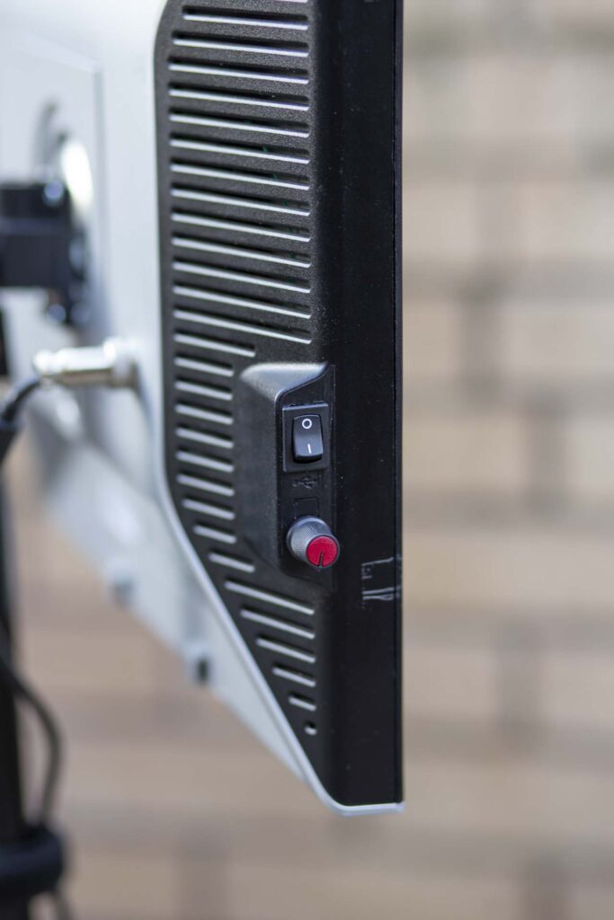
Doing a bit of butchery to the monitor case, the hole for the upper USB connector on the left side was opened up to fit the power switch, and the lower USB port was closed off with black styrene sheet, then drilled out with a 6mm hole to fit the brightness potentiometer. By an amazing stroke of luck, with this model of monitor both of those components fitted neatly behind the monitor’s inner metalwork without any modifications.
The next addition to the monitor case was the power connector – I used a GX16 2-pin socket for this as it should make finding the correct laptop power supply easy. It’s the one with the matching plug! The power socket is fitted in 17mm a hole drilled in the back of the monitor housing next to the stand mount.
The final modifications to the monitor case were all about blocking off the holes left by bits that were no longer present: holes for the front panel switches and the monitor connections were covered over with black styrene sheet. This was glued in place with Tamiya Extra Thin Cement (87038): when it was set it was strengthened with 5-minute epoxy round the edges.
The back part of the inner metal housing was discarded – it would have potentially made the stand mount a bit stronger, but weighing in at over half a kilo for a small gain in strength it had to go. The light stand mount (with hot shoe removed) was fixed to the back of the monitor body using four bolts though casing and the detachable mounting plate: that should be strong enough.
Finishing it off
Wiring: both sides of the power socket were connected to the power switch and the other sides of the switch to the input side of the LED driver module. The ouput of the LED driver was connected to the panel and the indicator LED (and resistor) on the front bezel.
Small Neodymium magnets were glued (using 5-minute epoxy) to the inside of the front bezel at the top corners and at the bottom – these should make it easy to fix on a diffuser panel if/when I get round to making one.
With the wiring connected assembling was just a question of fitting the front bezel over the tray with the LEDs and electronics and snapping the back casing on. The end result looks pretty reasonable – it’s a monitor, but not as we know it!

As far as performance is concerned, at full power the light output was measured at 2920 Lux at one metre, which is pretty respectable. This is what it looks like in daylight at about one third power:

Light output seems to be quite even and fairly soft, which is not a major surprise given the area of the light. That said, at some point I’ll make a clip-on diffuser to fit on the front.
4 thoughts on “Upcycled Monitor LED Light Panel”