Several of my photography project builds are based on the Arduino boards. These provide a very versatile and low-cost platform that mostly avoids having to design discrete electronics for basic sensing and timing functions. Getting set up to build with an Arduino is very simple and doesn’t need a background in electronics or computing. However, starting out can be a bit daunting if you’ve never used one before, so this is a quick guide to Arduino basics.
Note: this is not intended to be an exhaustive description or some sort of reference text. There are plenty of more in-depth guides available online. If you are looking for something more extensive the Arduino website (www.arduino.cc) is always a good place to start.
The Arduino Board
The first thing you’re going to need is an Arduino board. There are quite a wide range of models available (see the Arduino site www.arduino.cc/en/Main/Products), so how do you pick the right one for your project? The fact is, it doesn’t matter much which you use and the most basic are probably going to be able to handle most photo related projects. Some boards have more powerful processors and/or more input/output pins, but for most photo related projects these aren’t really necessary. The good news with Arduinos is that the code is pretty much the same as you move from board to board. So if you decide to change boards for some reason you’re not faced with a major code rewrite.
In the interests of keeping things simple, in this article I’m going to focus on just two models: the Uno and the Nano, which are the ones I use for most of my Arduino experiments. Technically they’re up to the job, and they have the added benefit of being pretty cheap, so building one into a device that’s only going to be used occasionally isn’t an issue.
The Uno is probably the most widely used of the “full sized” Arduino boards and features 14 digital input/output pins and 6 analog inputs – that’s more than enough for any of the projects I’ve built so far. The Uno also features the standard Arduino headers, making it simple to plug in a massive range of shield boards without having to get involved in soldering up boards and cables. Supply voltage is 7-12 volts, and there’s a built in regulator to give the 5 volt operating voltage. The genuine Arduino version of this board can be bought from Amazon amongst other places. Cheaper clones are available, but can suffer from driver problems (which can make it very difficult to connect to the development computer) and potential reliability issues, so are probably worth avoiding when you’re first starting out.
If you need something a bit more compact for a particularly small build, try the Arduino Nano. It features 22 digital input/output pins and 8 analog I/O pins, all in a package that’s just 18 x 45mm, and only consumes 19mA. Again, supply voltage is 7-12 volts.
The Other Stuff
Apart from the Arduino board, you need only the development environment and a USB cable to connect the board to your development machine. The development environment, which is free and available for multiple operating systems, can be downloaded here: https://www.arduino.cc/en/Main/Software.
Once you’ve run through the install process you need to connect the Arduino board to your development machine via an appropriate USB cable. Different Arduino boards use differing USB connectors: for example the Uno uses a USB Type B and the Nano a USB Mini B connector. When your project is under development the Arduino board can run from the power supplied by the USB connection so there’s generally no need to rig up a power supply at this stage, although this will depend on what other electronics are also needing to be powered.
Run the development environment and connect to the Arduino – this isn’t always straightforward (based on experience running under Windows) due to the way com ports get assigned to USB ports. Click the “Tools” dropdown and select the correct Arduino board from the “Board” list, then click “Tools” again and select the correct com port from the “Port” list. It may not always be obvious which com port to select – sometimes there are more than one listed with the Arduino model against them, and other times there is no Arduino model listed against the com port at all, just a numbered list of ports. In this case, if you’re running under Windows run the Control Panel and select “Device Manager”. On the list if devices expand the “Ports (COM & LPT)” items and it should be possible to see the com port number for the Arduino board. Select this port back in the Arduino development environment.
Before getting involved in any serious programming it’s probably worth doing a quick check that everything is functioning correctly using one of the sample sketches supplied with the Arduino IDE. These can be found in the “File” menu under “Examples”: in the “01 Basics” list there’s a program called “Blink” which, when running will flash the Arduino’s on-board LED.
Once you’ve selected this you can compile it using the tick button and upload it to the board using the arrow button. It should give a message saying “Done uploading” if it’s been successfully sent to the Arduino. At this point it will start running on the board and the on-board LED should now repeatedly turn on for one second and off for one second. The timing of the flashes can be modified by changing the values in brackets in the delay(1000) statements: 1000 being the time in milliseconds. If you change these recompile and upload and the flash pattern will change based on the on/off delays you’ve entered in the code.
After that confidence booster you can type or copy the code (or sketch in Arduino speak) for your real application into the Arduino IDE.
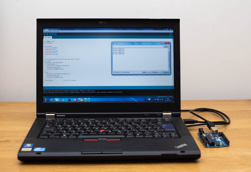
A couple of useful debug tools built in to the IDE are the Serial Monitor and Serial Plotter. If there’s any serial output from the Arduino sketch (created by adding Serial.println statements to the code) it can be viewed on the development computer using the serial monitor. This can be started by clicking the magnifying glass icon at the top right of the Arduino IDE window. When developing new code this serial debug is very useful to see where it’s all going wrong. You can see the serial monitor window on the right hand side of the display in the simple development setup pictured below.
The picture also illustrates the point above about serial port selection in Windows. Com 20 probably isn’t the port you’d expect when the only USB device plugged into the laptop is the Arduino.
Newer versions of the Arduino IDE also have a serial plotter which plots levels against time if the right print statements are included in the code – this can provide another useful level of debug.
By the time you get here you will hopefully have a working Arduino board which you can program from the development device of your choice. Obviously a stand-alone board isn’t going to get very far as the controller for your photographic projects, but it is the place where all the heavy lifting will be done. In the individual projects I’ll describe how to add inputs to allow triggering from various sensors and outputs to trigger cameras, flashes, valves and the like.
4 thoughts on “Arduino Basics: How To Get Started”