I did a 365 photo project a few years ago in a bid to improve my photography by forcing me to take more pictures. The first and last quarters of the project covered the times of year when the hours of daylight are limited at these latitudes and the weather is often not conducive to trying to shoot outside. As a result I spent a lot of time doing indoor shots. One of the recurring themes involved water: making waves, bubbles, drops and splashes, and trying to catch them being interesting using flash.
Drops and Splashes
Focusing on the drops and splashes, I did manage to capture some reasonable shots. However, it was a very hit and miss business timing-wise, with a lot of frames of a still water surface with no water drop at all. And I never got close to capturing one of those shots of a drop hitting the splash from the previous drop. So how do you capture water drop shots without missing the action most of the time?
It’s all about getting two drops the right length of time apart and managing to trigger the flash just as they collide. This is either going to take:
- an incredible amount of skill, both in the set up and timing of the individual shots, or
- a massive amount of luck, or
- some electronics to improve the odds in your favour.
Taking the third option, you can buy off-the-shelf solutions like the Mumford Time Machine and Drip Kit, but these are quite expensive. As an alternative why not make your own DIY Arduino drop controller? This is, after all, exactly the sort of application Arduinos are very good at.
There are several ways to provide the user interface to enter the drop size and timing, but for this build I opted to keep the unit self-contained by using an Arduino keypad display shield. This may not give the most sophisticated user experience, but it has the advantage of only needing to develop code for the Arduino rather than having a second set of code (and development environment) for phone, tablet or computer.
Parts List
What you’re going to need (the list looks long, but the components are fairly cheap):
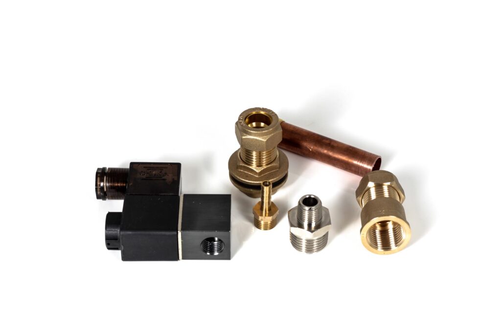
- Solenoid water valve
- Water reservoir (plastic food container)
- 15mm x ½” tank connector
- Short length of 15mm (½”) copper pipe
- 15mm to ½” female screw thread straight adapter
- ½” BSP male to ¼” BSP male reducing adapter
- Flexible silicone tubing (aquarium airline tubing should do the job)
- Silicone sealant
- 15mm plastic pipe clip
- Some sort of stand to mount it all on
- Arduino board – most of the full size varieties should work (ie the ones that you can plug a shield board into): I used the Uno as I generally have at least one of them lying around
- Arduino display/keyboard shield
- Prototype Arduino shield board
- 4N35 optoisolator x2
- 390 ohm resistors x2 (it’s probably worth getting a resistor kit as it avoids being constantly delayed waiting for orders of individual resistors to be delivered)
- MOSFET switch module – for a neater build it would be possible to put the MOSFET and supporting circuitry onto the prototype shield board, but I had a module based on the IRF520N MOSFET in my Arduino components box so used that instead.
- 7812 voltage regulator
- 470nF capacitor x2
- 2.5mm stereo jack socket for camera trigger cable
- 2.5mm mono jack socket for flash trigger
- DC power jack socket x2 (for input power and solenoid connection)
- Power supply: 12 Volts DC at 0.5 Amps.
Plus, if you want to box the electronics:
- A project box
- Five push-to-make switches (four black, one red)
Software
While the hardware for the project is pretty straightforward, the major work was writing the software. The bulk of the code is the user interface, and that’s likely to be that case no matter whether the user-input part of the process is done using a computer, phone/tablet or the display keypad shield.
With the display keypad it involves taking input from the very limited keypad and displaying the values on the basic two-line display. This is perhaps not the most elegant solution, but it does make the system self-contained. The actual valve control part of the software is very simple – open valve, delay, close valve, delay …
Two Arduino libraries are used by the code for this application. The first is LiquidCrystal for interfacing to the keypad/display and the second is EEPROM to allow the parameters to be written to and loaded from the onboard EEPROM. These libraries need to be added in the Arduino IDE prior to compiling the sketch.
Software design parameters
The first thing to decide is what parameters the user needs to control. My assumption here was that the user needs to be able choose one, two or three drops, to control the size of each drop (ie. the time the valve is open) and the spacing between drops (the time the valve is closed between drops). The camera output (with the camera on bulb) is going to trigger at the very start of the timing cycle, but a separate flash trigger output will fire a user-defined time after the last drop is released. This should ensure that the action is captured by a short bust of flash when the collisions are actually happening.
Drop size is defined by a valve opening of 1 to 99ms, and time between drops by a valve closure of 1 to 999ms. The time for a drop to fall is going to vary with the height of the dropper, so it seemed like a good idea to allow a period of up to nearly a second between drops for flexibility. Flash delay is also programmable in the range 1 to 999ms.
My source code for the project can be downloaded here. It comes with no guarantees, but should be a good starting point for anyone building a keypad/display shield based dropper.
Driving the software
Programming the system is fairly simple: scroll through the options using the up/down keys and when the parameter you want to modify is on the top line of the display, select it using the select key. You can then modify its value using the up and down keys, and can change the size of the increment/decrement with the left and right keys. Hitting the select key again allows you to go back to scrolling through the parameters.
If you press the select key when “Fire” is on the top line of the display, the current parameters are written to the on-board EEPROM, the display backlight turns off and the trigger cycle you’ve programmed commences. When the trigger cycle is complete the backlight turns on.
Hardware
The Wet Bits
This is pretty straightforward, but will depend a lot on the valve and water reservoir you’ve chosen. My reservoir is a round, plastic food container with a snap on lid. I cut a hole in the bottom to fit the tank connector, then fitted the piece of copper pipe to this, followed by the 15mm to ½” female adapter, the ½”to ¼” adapter and the valve. Putting it together I used plumbing jointing compound on the compression fittings and PTFE tape on the screw threads. In what’s effectively a zero pressure system this was probably unnecessary and it should be ok to couple the plumbing parts ’dry’.
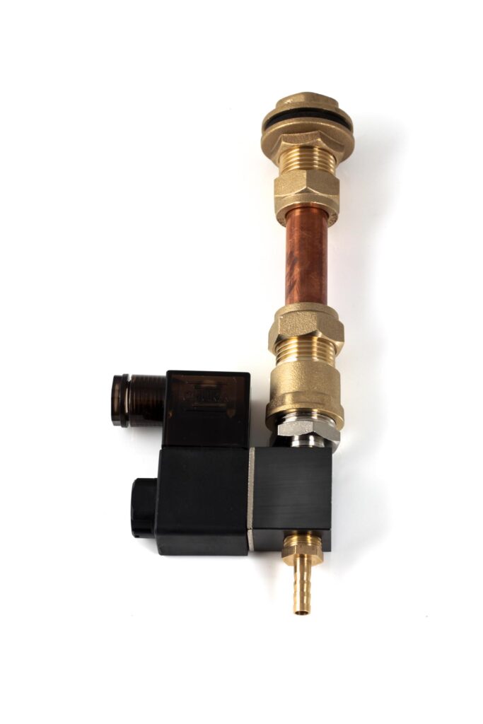
I cut a small hole in the lid of the container and fixed in a short length of silicone tube that reached close to the bottom when the lid was in place. This is a Mariotte syphon, which keeps the pressure in the container constant as the level inside drops. This should mean that the drop size will remain constant for any given valve-open time as the reservoir empties.
Holding it all up depends on the stand you’ve chosen. I used the column from an old enlarger I had lying around from the days when I used to do black and white printing. The valve/plumbing is attached by a 15mm plastic pipe clip which snaps on to the length of copper pipe between the valve and reservoir.
The Dry Bits
To keep the build simple I originally planned to use a stackable relay shield board to control the solenoid valve, camera shutter and flash. However, the display/keypad shield uses most of the Uno’s digital pins, including three of the four used to control the relays on the shield board, so that was a non-starter.
It would be possible to use a non-stackable relay board mounted separately but I opted to go for optoisolator and MOSFET based triggers instead, as they are far faster and give more consistent timing than relays. A couple of low power optoisolators provide the triggering for camera and flash and a power MOSFET is used to power the solenoid coil.
Working around the digital I/O pins taken up by the display/keypad shield, there are still enough outputs available to the control the valve, camera and flash. In my software they’re set up as follows:
- Valve control – Pin 2,
- Flash trigger – Pin 3,
- Camera trigger – Pin 11.
The optoisolators were built onto the Arduino prototype shield board, giving a nice compact stack of boards for building into the case when it was all finished and tested. The MOSFET module is very small and was mounted separately on the case close to the solenoid trigger socket.
Schematic
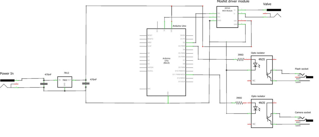
One final piece of electronics hardware I added was a voltage regulator. I was planning to power the system with an old 12 Volt DC supply I had lying around. I’ve no idea what it came from as it’s one of several that was separated from the obsolete bit of kit it powered long ago. Typically for these type of units it gave an output voltage reading of about 16V with no load applied.
This is pretty high for the onboard regulator on the Arduino, and is higher than the suggested voltage for the valve. To drop it down to a regulated 12 volts only required a SG7812 voltage regulator and two capacitors. These regulators can deliver an amp, which is plenty for the Arduino and valve.
A schematic for the complete system would make this all look a lot more complicated than it actually is. Using the LCD keypad shield makes the circuit diagram of that part of the unit irrelevant, since you only have to plug the parts together. The circuit diagram for the other add-on parts is pretty simple, comprising a three-component voltage regulator, two two-component optoisolator circuits for the camera and flash triggers and the MOSFET module to control the valve. Connecting this lot to the Arduino gives this circuit :
Setting It Up
By now I had a system that’s capable of controlling the number, size and gaps between drops and the relative timing of the flash, so it was time to get it set up to produce some good splash shots. The starting point for this was the basic physics equation:
s = ut + ½ at2
where:
s is distance (ie the height the drip starts above the target),
u is initial velocity, which in this case will be zero,
a is acceleration due to gravity (9.8 m/s2)
t is time (ie what we’re trying to work out)
Since the water drop is starting from a standstill the first part of the right hand side of the equation is zero, so this simplifies to:
s = ½ at2
Turning that around to solve for ‘t’:
t = √(2s / a)
With a height of 320mm (I set the end of the brass valve outlet at 300mm above the water surface, but the actual distance for the calculation should be the distance from roughly the bottom of the valve block to the water surface) this becomes:
t = √((2*0.320) / 9.8)
Which works out at a time of 0.2555 seconds for the drop to hit the water.
That’s the theory, so putting it to the test I used a single drop with a size of 20ms and a flash delay reduced slightly to 245ms. Theoretically that should catch the drop just before it hit the water. In practice the following picture was what I captured:
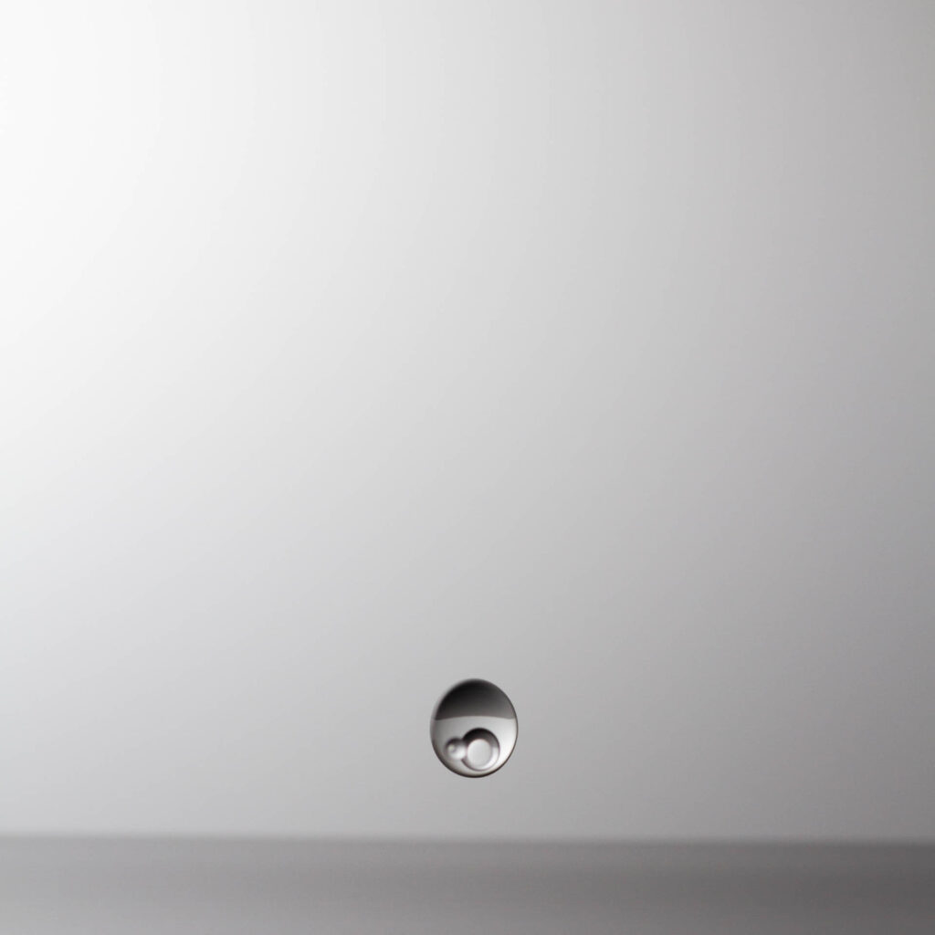
Well, that was encouraging!
Extending the flash delay (in this case to about 400ms) captured the post-impact column of water that was shaping up ready to be hit by another drop. A second drop delayed by about 100ms started to give the sort of splash patterns I was hoping for when I set out to build the system.
Bear in mind that when you start to use multiple drops the flash delay should be reduced, as the way I wrote the software it’s the delay after the last drop that that triggers the flash. Here’s a two drop splash with drop sizes of 10ms and 10ms, a delay of 100ms between drops and a flash delay of 255ms:

Note: it’s well worth keeping a record of the settings you’re using for each shot, as juggling the timing of the inter-drop delay and the flash delay can sometimes appear to defy logic as you tune them up over a series of shots.
Lighting
This is a slight aside from the project build, but if you don’t light the splashes properly you’re not going to get decent results. The good news is that you only need a single strobe pointing at (or through) the background, but it must have a very short duration to freeze the motion of the drops and the splash pattern. Most traditional studio flashes don’t give a short enough flash burst, although some of the newer ones that have IGBT circuitry will be ok. Portable strobes with a manual power setting should generally work fine.
The strobe should be set to manual power mode with (close to) its lowest power setting selected, as this gives the shortest flash duration. The unit I’ve done most testing with is a Yongnuo YN568 EXII – apparently this has about a 1/20,000 second flash duration at 1/128 (minimum) power. That said I’ve also used several of my older strobes at their lowest power settings: Canon 540EZ (at 1/128 power), Canon 430EZ (at 1/32 power), Canon 420EZ (at 1/32 power) and an Achiever 632LCD (at 1/16 power). All appear to have a short enough duration to give a workable image.
Boxing the Electronics
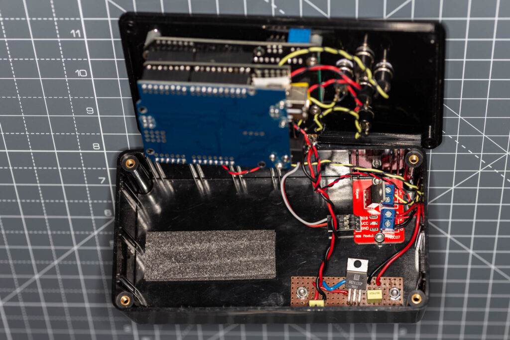
Once the electronics was working I used it for several sessions with the Arduino shields and the two other boards just lying on the table at a safe distance so they wouldn’t get wet. However, as a long-term solution this isn’t ideal since at some point the boards are liable to get splashed or shorted and the wires broken or otherwise damaged. To avoid this I put the electronics in a project box. This also gave the option of replacing the horrible push-button switches on the display board with something a bit more tactile.
The project box needed a bit of surgery to start with – a rectangular cut out for the display, five holes for the switches (up, down, left right and select) and a further four for power-in, solenoid, camera trigger and flash trigger. In addition there are four holes for attaching the Arduino stack and two each for the MOSFET module and power regulator. With those cut and drilled there’s just a bit of soldering for switches and sockets, followed by bolting the boards into the box.
Boxed, before closing up, the final stack of Arduino, prototype shield and display/keypad, with external MOSFET module and voltage regulator looks like this:
The Setup
Working with a single strobe, my setup looks like this:
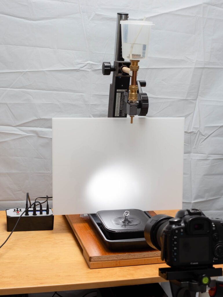
The background is a sheet of opal perspex with the strobe firing through it. The black tray holding the water is the plastic type you get ready-meals in, while the second one below it catching the overflow (and allowing me to fill the water tray right to the top) is just a regular oven tray.
Results
In use it takes a while to work out the timings to get decent results, but once you start to understand the way the splashes form it’s reasonably easy to make interesting patterns. There can be a bit of variation in the splashes produced with exactly the same timings – several factors may be playing out to cause this:
- variability in the timing of the valve opening (it is electro-mechanical after all),
- drop size: if the drop size is set too large a secondary drop is sometimes produced, which creates unpredictable results,
- variation in the way the drop comes out of the valve’s output port,
- residual liquid in the valve outlet from the previous drop.
That’s my guess anyway. Below are a few of the images produced in the first few sessions using the system.


Update
Prior to moving onto this new domain there were a lot of positive comments about this unit. However, in their feedback Alex and JM noted that the way I was writing parameter values to EEPROM was wrong. I was writing the parameters as byte values, although in the sketch they are integers. This meant that when delays were set to over 255ms, the values being loaded at system startup were wrong. This was never an issue I’d noticed myself as I had never used a delay that long.
I have finally fixed this issue and the Arduino sketch linked above has been updated to reflect this, so should now be good for anyone using longer delay times. For reference I ended up using the EEPROM put and get commands (rather than write and read used in the original).
3 thoughts on “How to Make a DIY Arduino Drop Controller”