If you want to capture pictures of wildlife, one of the big challenges is getting close enough to your subject. This is likely to involve getting into position, camouflaging yourself or building a hide to sit in, and waiting for hours (or days) for your elusive subject to turn up.
For those of us that don’t do this for a living, but still want to attempt to get a few decent wildlife pictures for our portfolios with modest time and equipment budgets, this build should effectively let you set up your camera like a trail cam and retire to a safe distance while the electronics does the work. You still need to have an understanding of the subject’s behaviour to get set up in the right place and time. As long as you have that, it should be possible to get some reasonable shots without having your finger on the shutter release all the time.
The basis of this project is an Arduino, with a passive infrared trigger as a motion sensor and an optoisolator to fire the shutter. You could argue that this project is a waste of the power of an Arduino, as you could build something similar with just a PIR and an optoisolator. However, I decided to use an Arduino so that I can expand the functionality in the future. I haven’t quite decided what that expanded functionality might be yet, but the platform’s there just in case.
To make this reasonably field-friendly the electronics is enclosed in a plastic electronics case, although I didn’t try to make it particularly weatherproof as the SLR and flash (if you’re using one) would still need additional protection if they’re being left out in the rain.
Parts
- Arduino board: pretty much any version should do as the project only needs one digital input and one digital output. For compactness I used the Arduino Nano.
- PIR sensor: I started out using the HS-SR505 module as it is very compact, but I had a few issues with it and switched to the bigger, but more tunable HC-SR501 after the first prototype.
- Optoisolator (aka optocoupler) chip: I used the 4N35.
- Resistor: around 390 ohms, but will vary depending on the optoisolator used. If you buy a resistor kit with a decent range of values you should have it covered (and you’ll have enough for your future projects too)
- Veroboard or equivalent.
- 2.5mm stereo jack socket.
- Power rocker switch.
- Battery: the Arduino Nano board has a built in voltage regulator to give its internal 5 volt supply, and needs 7 to 20 volts applied to the Vin pin (pin 30). Going for the lower end of this range, this gives several power options including:
- 6xAA battery clip: gives 9 volts with alkaline batteries or 7.2 volts with NiMh rechargeables,
- PP3 battery: 9 volts,
- 2S or 3S lithium polymer rechargeable battery: 7.4 volts or 11.1 volts respectively.
- Plastic box for housing. There are all sorts of suitable boxes available from electronic component suppliers, eBay and Amazon: for this project I used a black E77 project box (124 x 72 x 37mm).
- Foam tape.
Electronics Prototype #1
It’s easy to quickly put together a breadboard prototype for this build as it’s very simple from a wiring perspective. This proved to be good news as the first prototype did highlight a few problems. For compactness I started out with an Arduino Nano board, which with the original choice of PIR sensor would potentially fit into a very compact case.
The first problem I encountered was that the PIR sensor appeared to be permanently detecting movement: I wasn’t sure if this was a levels or noise issue, so I swapped out the Nano for a Leonardo. The problem was solved instantly so I decided to continue with the Leonardo for the time being.
A couple of further issues were identified that appear to be attributable to the HS-SR505 PIR sensor. The first is that it seemed to be very sensitive to electrical noise, which may have been the cause of the problem with the Nano board. The code to interrogate the PIR is very simple, but did highlight a second issue. When the PIR is triggered by detected motion its output stays in the active state for something like 7-10 seconds. That may be a bit too long and with the HS-SR505 there doesn’t appear to be any way of reducing this, or of adjusting the sensitivity. Maybe the answer was a different PIR sensor …
Electronics Prototype #2
For the second attempt I bought in a few HC-SR501 sensors (they are pretty cheap, so it’s good to have a spare or two). The HC-SR501 allows adjustment of sensitivity (3-7m range) and time delay (variable from about 3 seconds to approximately 5 minutes) via a pair of variable resistors on the pcb. There’s also a jumper to allow selection of single trigger or repeatable trigger. All in all, a lot more configurable than the original sensor.
For the breadboard prototype I switched back to using the Arduino Nano. Wiring the sensor up to the Nano via one of its digital pins triggered fine as soon as the time delay on the PIR had been set to the minimum (by turning the pot fully anticlockwise).
Camera triggering is handled by a 4N35 optoisolator connected to one of the Nano’s digital output pins. This requires a resistor in series to get the right current.
Boring electronics engineering bit alert, skip this if you’re not of a technical disposition:
[Referring the 4N35 device datasheet, the LED in the 4N35 needs a forward current of around 10mA, and at this current, the typical forward voltage is between 1.1 and 1.2 volts at an ambient temperature of somewhere below 25°C. Given that the Arduino’s HIGH output level is nominally 5V, the drop across the resistor will be 3.9V to 3.8V. Therefore the resistance should be voltage/current or 3.9/0.01=390 ohms or 3.8/0.01=380 ohms. I used a 390 ohm resistor as it’s a standard value and I had some in stock.]
The breadboarded version of the prototype looks something like this:
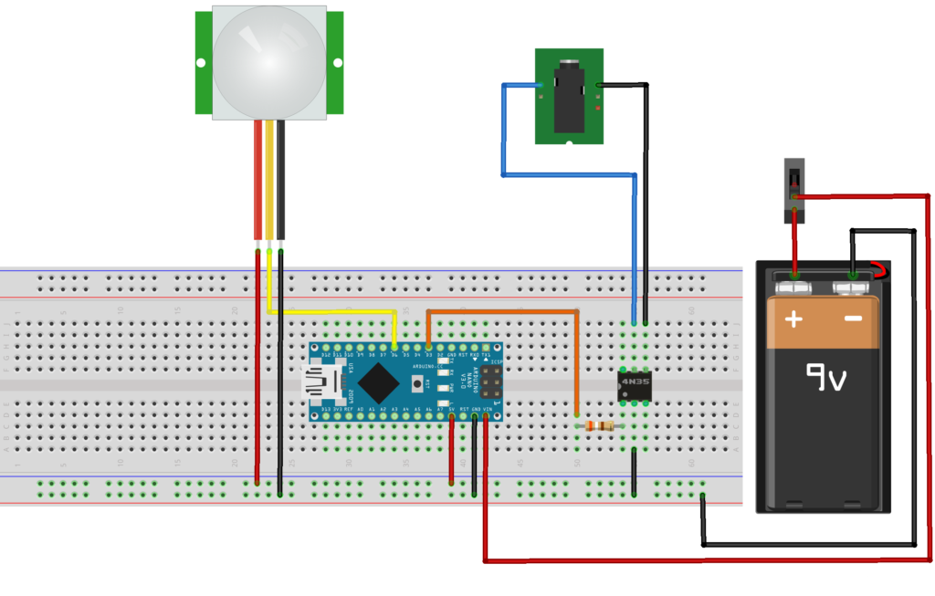
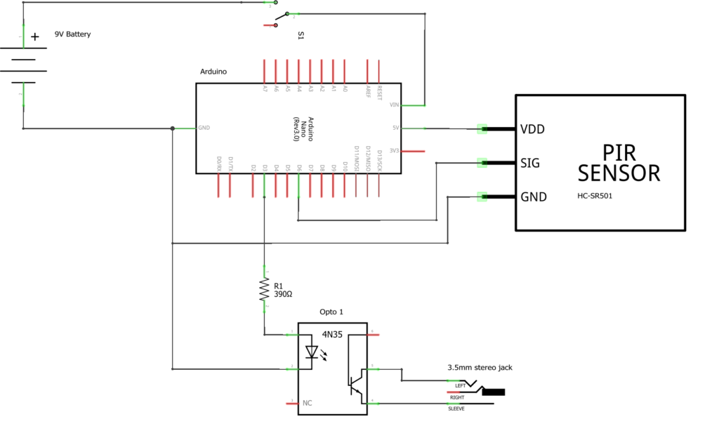
And the associated circuit diagram is shown below:
Arduino Code
The software for this is just about as simple as it gets: first initialize the Arduino and then loop (forever), polling the input pin. If it goes active, switch on the output pin for a short period. The code looks like this :
int LEDpin = 13;
int pirValue;
void setup() {
Serial.begin(9600);
pinMode(6,INPUT);
digitalWrite(6,LOW);
pinMode(3,OUTPUT);
digitalWrite(3,LOW);
}
// the loop function runs over and over … forever
void loop() {
pirValue = digitalRead(6);
if (pirValue>0) {
Serial.println(“Motion detected”);
digitalWrite(3,HIGH);
digitalWrite(LEDpin,HIGH);
}
else {
Serial.println(“Nothing happening”);
digitalWrite(3,LOW);
digitalWrite(LEDpin,LOW);
}
delay(1000); // wait for a second
}
Copy that code into the Arduino IDE, compile it and upload it to the board. If you haven’t used an Arduino before there are tons of resources online to get you started. Alternatively you can take a look at the concise (and very superficial) guide I put together for just this reason. It should contain enough information to get you through a simple project like this, and can be found here.
There are a couple of debug features added to the code to make it easier to check that the sensor is working and adjusted correctly. The “Serial.println” statements are useful when the Arduino is still connected to the computer, sending messages that can be displayed using the Arduino IDE’s serial monitor window. The “digitalWrite” to the LEDpin flashes the on-board LED when motion is detected.
Building it
Once the prototype is working on breadboard, it’s time to get the soldering iron out. You’ll need to solder the optoisolator and resistor onto the veroboard and connect the battery leads, switch, output socket and the signal and power leads to the Arduino board. To keep things neat I mounted the Nano on the veroboard as well, using a piece that was long enough to slide into the mounting slots in my project box. That avoided having to work out a separate method for mounting the boards.
Note: the output socket only needs the shutter and ground pins connected – not the focus pin, as the lens will be pre-focused and switched to manual mode.
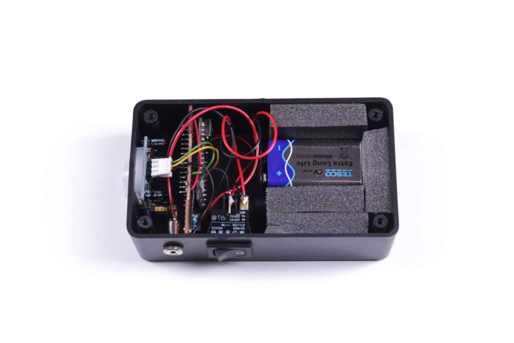
Once the electronics has been built and given another quick test to make sure nothing’s gone awry in the assembly process it’s time to put it all into the case ready for use. I used strips of 10mm thick foam tape either side of the battery to keep it in place (it’s the heaviest part if the unit, so it needs to be stopped from rattling around and damaging the electronics and wiring).
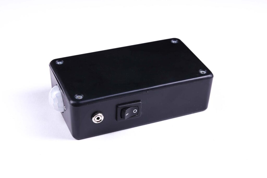
And the completed trigger unit, boxed up and ready to go looks like this:
Using it
Power up the PIR trigger and plug the camera trigger cable into the output socket. The camera should be set to manual focus, and pre-focused on the target area. The trigger has a single output to release the shutter and does not activate autofocus. Position the PIR trigger and fix it as well as you can, pointing at the target area – check both the trigger and camera are set correctly by moving your hand, foot or face (as appropriate) in the target area and seeing if a) the camera fires, and b) if the shot is sharp. Adjust until the results look reasonable, then retire to a safe distance and see what transpires.
The PIR sensor’s area of detection is quite wide (110 degree cone) so you may want to limit it using some sort of sleeve over the unit to avoid it being triggered by movement that is outside the area visible to the camera.
3 thoughts on “DIY PIR Camera Trigger Unit”