If you’ve ever tried to capture splash shots of objects dropping into a glass tank of water you’ll know that catching the action at the right moment is very hit-or-miss (mostly miss in my case). While it’s something that you probably get better at with practice the hit ratio is still likely to be fairly low. This means lots of mopping up and tank-glass cleaning after shots where nothing useful was captured.
To increase my proportion of usable shots I bought a Triggertrap Arduino shield a few years back (when it was still available). In use I found it was a pain to set up, particularly getting the laser and sensor aligned properly. In fact I enjoyed using it so little it’s been sitting in a cupboard gathering dust ever since my first couple of sessions with it. I didn’t have much joy with its sound triggering capabilities either.
Fast forward to the present and I decided it’s time to set up more splash shots and do it in a more controlled fashion. There’s a small glass fish tank (formerly the residence of my younger son’s goldfish, which has gone to a better place) sitting on a shelf in the garage, and I’ve got drawers full of Arduinos and opto-isolators. And with a bit of luck a properly designed photogate camera-flash trigger can be used for more than just splash shots …
Requirements
- Laser and sensor should be easy to set up and align, so they need to be packaged in a way that’s easily attachable to whatever they have to be mounted on,
- Laser module and sensor should both be remote from the control box (ie. plugged in via cables) unlike with the Triggertrap,
- There should be a user adjustable delay between beam break and camera/flash triggering,
- There should be two modes of operation:
- Camera mode: mostly for use in daylight conditions. The camera is triggered after a delay from beam break. If flash is going to be used it will be triggered by the camera.
- Flash mode: for use in dark conditions. The camera (on bulb setting) is triggered when the controller is armed, flash is triggered after delay from beam break.
Parts List
Parts needed to put this together are:
- Arduino to do all the clever stuff – I used an Arduino Uno for this build,
- Rotary encoder module to set the camera/flash delay,
- Nokia 5110 LCD display to show delay value and system status,
- Push button switch (single pole) to set the mode,
- Push button switch (single pole) to arm the system,
- Arduino laser module (beam source),
- BPW34 photodiode (beam sensor),
- A few resistors: 6 x 10kΩ, 1 x 1 kΩ, 2 x 390Ω
- Two 4N35 optoisloators to trigger camera and flash,
- Battery clip to supply the power: I used a 6xAA clip, which gives 7.2V with NiMH rechargeable or 9V with regular alkaline batteries,
- All the usual finishing bits (project box, sockets, on/off switch, foam tape, etc.),
- Very small project box (x2) to hold the laser and sensor.
Electronics
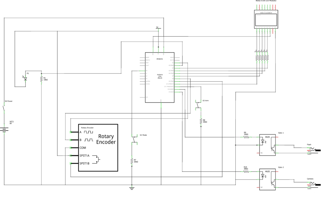
The Nokia 5110 LCD is a great little display if small and monochrome is what you’re looking for, but it’s a 3.3V unit so for most Arduino boards you need to add series resistors to ensure the 5V digital outputs don’t cause any damage. A 1kΩ does the job for the SCE pin, and 10kΩ for RST, D/C, DN and SCLK. The Uno has a 3.3V power output, so there’s no need for any additional regulation circuitry to power the display.
For this project I used a rotary encoder for setting the delay, as these are generally a lot quicker to operate than push buttons: just rotate the knob clockwise to increase the delay and anticlockwise to reduce it. These encoders often have a built in push switch, so I’ve used this to reset the delay to the default value.
The Mode and Arm pushbutton switches are connected between ground and the digital (or analogue) input pins: configuring the pins as INPUT_PULLUP enables the Arduino’s internal pull-up resistors, so no external pull-ups are needed.
For the output side there are two 4N35 optoisolators for the camera and flash triggers, both with inline 390Ω resistors (see PIR Trigger article for the explanation of how the resistance value is calculated if it’s of interest).
Laser and Sensor
Using a laser module like the one listed above means you only need to supply 5 volts and ground. Both of these are available on the Arduino board, so all it takes is two wires to get it connected. The module is very small and is mounted on a pcb, so is easy to box up for mounting as per the first requirement above. That’s the light transmission side sorted.
For the light sensing side it’s only slightly more complicated: the cathode of the photodiode is connected to 5V and the anode to the Arduino’s input with a 10kΩ pull-down resistor to ground. Again small and easy to box up (more about that later).
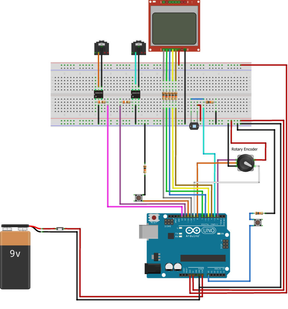
The breadboarded test version of the circuit looks something like this:
The complete circuit diagram is shown below:
Software
The code for this project is slightly different to the PIR Camera Trigger and Drop Controller projects as it uses interrupts for both the rotary encoder and catching the beam break.
The reason for this is that both of these inputs are relatively timing-critical, so if the software is polling the encoder and sensor in a loop where most of the time is being spent doing something else (like updating the LCD display, which is a relatively time consuming process) it might mistime or completely miss an important event.
The way a rotary encoder works (a description can be found here) this can cause it to decrement when it’s meant to be incrementing, which can get frustrating. With the beam break detection it’s liable to lead to inconsistency in the results, including completely missing beam breaks. Luckily the Arduino Uno has two external interrupts which is enough for this application (some other models of Arduino have more).
Arduino External Interrupts
On the Arduino Uno pins 2 and 3 can be used to generate interrupts. These can be set to trigger in four modes: on a rising edge; on a falling edge; on any change, and on a low level on the interrupt pin. In the Arduino sketch, interrupts are set up in the “setup()” routine using the following statements:
attachInterrupt(digitalPinToInterrupt(CLKpin), isr, LOW);
attachInterrupt(digitalPinToInterrupt(SPDpin), isr2, FALLING);
The first of these statements is for the rotary encoder and makes input pin 2 (CLKpin) cause an interrupt when its state is low. When the code is in the main loop, a low signal on pin 2 will trigger the interrupt and execution will jump to the interrupt service routine “isr”. It returns to the main loop when the code in “isr” has been executed.
The second statement makes input pin 3 (SPDpin) cause an interrupt on a falling edge (high to low transition), which is what happens when the beam is broken. This time interrupt service routine “isr2” is called (as you can see, I got very creative when I named the interrupt service routines!).
Interrupt Service Routines
The interrupt service routines are short, as they pass back global flags to the main loop rather than doing anything too time consuming inside the interrupt handler itself. The variables used to pass data between the interrupt service routines and the main code body have to be declared as ‘volatile’. This is so they don’t get corrupted when execution switches between the interrupt service routines and the main code body.
Apart from the introduction of interrupts the software is pretty simple: the usual setup routine and the main loop to poll the non time-critical inputs and debounce the switch inputs, process any updates passed back from the interrupt service routines, fire the camera and flash triggers and (finally) keep the display updated.
A zipped copy of my Arduino sketch can be downloaded here. This has been updated to set the display’s contrast level in the setup routine. Nokia 5110 displays vary so there’s probably no contrast value that will work for all of them. To find the best contrast value for a particular display, the Arduino sketch in this post should help.
Building it
Since this is a piece of gear that has the potential to be used outside the studio, it’s worth building it into a reasonably robust box and powering it with batteries. Mine uses a 150mm x 80mm x 60mm project box, which is big enough to fit the Uno and battery clip and gives plenty of space on the front panel for display, switches, rotary encoder and connectors.
For the laser module and photodiode connections I used phono sockets to make them different from the camera and flash trigger, which use regular 2.5mm jack sockets. Aside from what’s already on the Arduino the only additional components are the resistors and optoisolators. Most of these are mounted on a small piece of strip board that has header pins attached so that it can be plugged into the Arduino like a shield board. To save a few wires between the front panel and the circuit board, the three pull-down resistors are attached directly to the switches and sensor socket.
Regarding the front panel, as well as labeling the controls and sockets it needed something to cover up the scuffs from drilling the holes. This time rather than the laminated paper panel I made for the drop controller I decided to print out the label template on glossy self-adhesive printer paper. To protect it and avoid the labels getting smudged I stuck a piece of clear self-adhesive Fablon sheet on the top. The result doesn’t look too bad, but to be honest I don’t think I’m yet close to reaching my optimum front panel labeling solution.
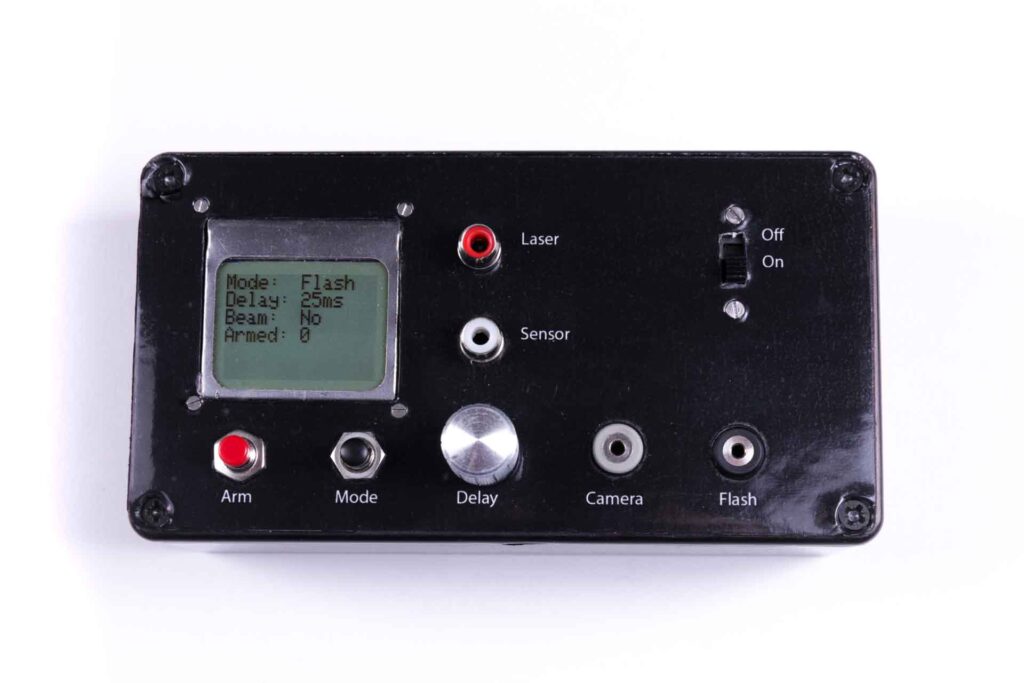
The finished box looks like this:
Boxing the laser module and photodiode
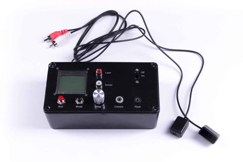
The aim here was to enclose them in small, lightweight rectangular units that would be easy to clamp or otherwise attach to any support or frame round the tank, or anywhere else I want a beam trigger. My solution was a pair of 26 x 18 x 13 mm sub miniature ABS plastic boxes. These are pretty small, and the laser module needed to have the three pin header de-soldered, followed by a bit of deft Dremel work to thin it down and remove the corners so it would fit around the lid screw post mouldings in the corners of the box.
Housing the sensor was a lot easier: the photodiode just had to be mounted on a small piece of veroboard to fix it in place. The completed units meet my original spec, and don’t look too bad either – this is them beside the trigger box:
Testing it
Plugging it all together and trying it out for the first time it seemed like a sensible idea to do a dry test. For this I used the classic ‘two soup can’ setup (it works with bean cans as well!). The laser and sensor were taped to the top of the cans and a ball dropped between them to break the beam. Here’s what I got in the dark using flash mode, with a 0ms delay for the first shot and 10ms for the second:
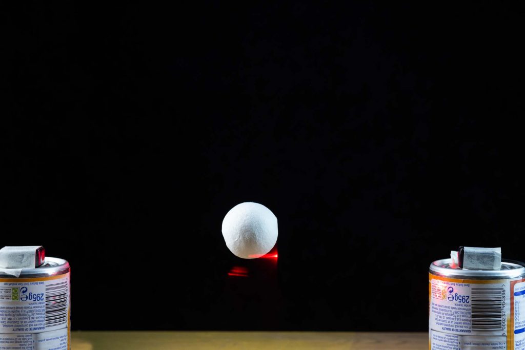
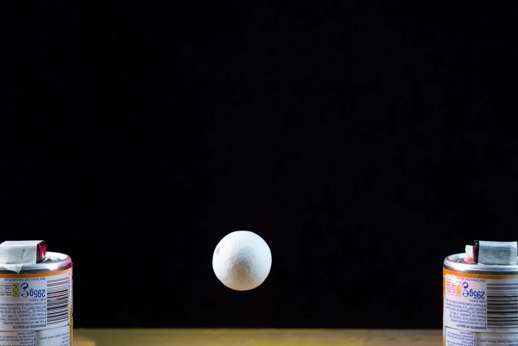
Encouraged by the results of the dry test I decided to get out the fish tank and try some splash shots.
Tank Setup
Allowing that lots of splashes were going to be made and things could get a bit wet, I laid a towel under the fish tank before it was filled. To keep the laser and sensor in place I made up a simple frame out of offcuts of wood with clamps at each end to sit on top of the tank. Both laser and sensor were wrapped in clear food wrap to keep them dry.
A boom arm was set up as a reference for the drop point to ensure some level of consistency, as the camera framing was going to be quite tight. I used my Genesis AS250 studio heads as they have IGBT circuitry and can give a very short (about 1/8000 second) flash on low power. The flash heads were set up either side of the tank, shooting through strip boxes.
The pictures below show a wide shot of the setup, together with one of the resultant splash shot. Again this was shot in the dark in flash mode. Height from drop point to water surface was roughly 300mm and the delay set to 110ms:
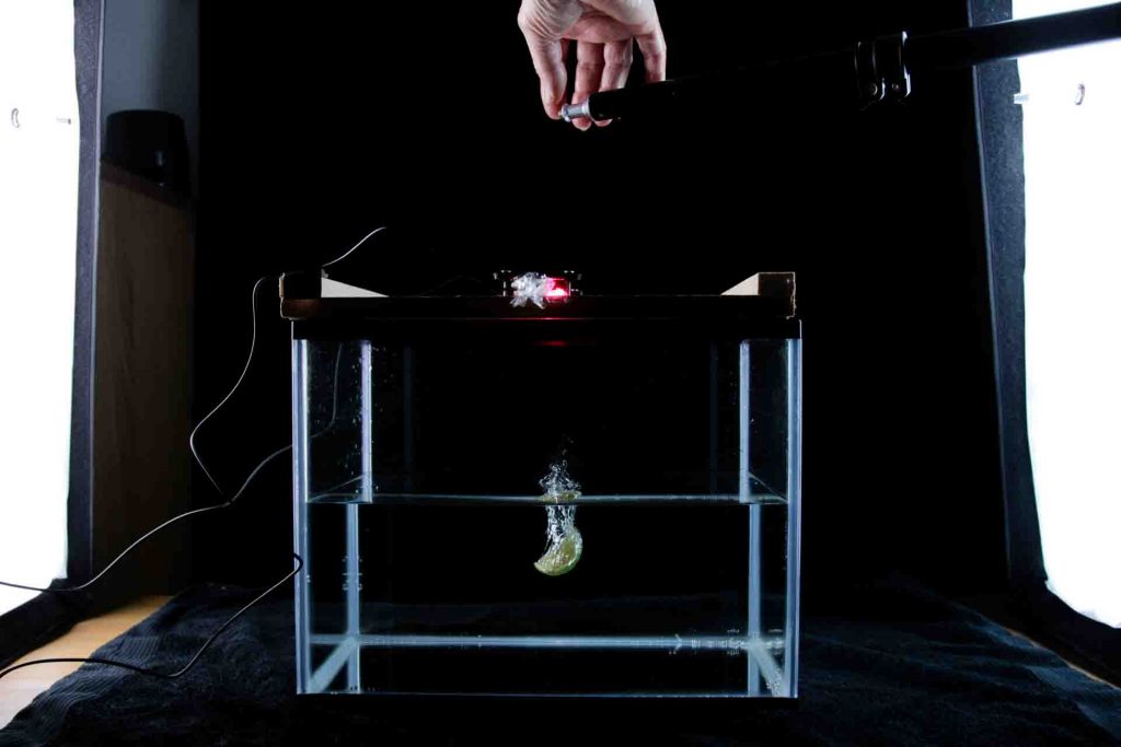

Note: the above was a ‘quick and dirty’ test, without cleaning the splashes off the glass between shots, or getting the lime released from exactly the same height each time.
Using it
If you’ve gone through the process of building a unit as described above you won’t have any problem getting it all plugged together correctly. However, while it makes sense to me, the way the software works may not be entirely obvious to everybody so here are a few pointers:
- The unit always powers up in “Camera” mode. That’s the mode for light conditions, so you set the camera’s shutter speed to something that works for the ambient light and the shutter will be triggered after the set delay when the beam is broken.
- Press the “Mode” button to toggle between “Camera” and “Flash” modes. “Flash” mode should be used in dark conditions with the camera’s shutter set to “Bulb”. With this mode, as soon as the system is armed the camera’s shutter is triggered, with the flash triggered after the required delay from when the beam is broken.
- Adjust the delay using the rotary encoder. The default value is 10ms – pushing the rotary decoder’s built in switch resets the delay to the default.
- Arm the unit by pushing the “Arm” switch – display will show “Armed: 1”. Unit will trigger when the beam is broken, at which point the unit again becomes unarmed. Pressing the “Armed” button when the unit is armed will also disarm it.
That just about covers everything I think, but feel free to ask if I’ve missed anything.
11 thoughts on “Make a Photogate Camera-Flash Trigger”
Dear John,
First off, huge thanks for publishing this build. I think it’s just what I’ve been searching for. I’m into high-speed flash photography and have just published for our club member a beginners tutorial for building an Arduino/piezo flash trigger https://conwycameraclub.com/tips-tutorials/diy-flash-trigger/
However, I’ve built your rig as per prototype but maybe I’ve misinterpreted the pinouts on the schematic/diagram as the only thing that works is my laser module. I’ve taken the liberty of adding to your diagram the pinouts from the screen I’ve bought and for the rotary encoder I found in a sensor kit I bought when I first discovered Arduino. Is it possible for you to confirm, or otherwise, the pinouts I’ve chosen for screen and encoder? Esp as my screen shows completely blank.
https://conwycameraclub.com/beam-trigger-problem/
I’m hoping I’ve gotten something wrong with the pinouts as nothing else I’ve checked bears any fruit.
I’ve checked my jumpers and put a meter across my wires to ensure correct value of resistors and continuity of wiring (suspected dodgy breadboard) but all appear fine. Via the above link I’ve also provided access to the sketch as it now looks after I figured out how to include libraries for Adafruit GFX and Adafruit PCD8544 as the sketch provided wouldn’t load until I’d done so (did I say I was new to this?).
Anyway, thanks again for publishing this, here’s hoping it’s something I’ve done as I don’t know how to check for screen functionality, don’t have a scope and wouldn’t know what to do with one.
Best regards,
Eugene Stevenson.
Hi Eugene,
It’s been a while since I put this together, so it’s not exactly fresh in my memory. I’d say the first thing to focus on is the display as it should come up with four lines of text as soon as it’s powered on if the sketch has been loaded onto the Arduino board and the wiring is good. I’ve just taken a look in the Arduino sketch and the pinouts listed in the code for the display are:
pin 4 – Serial clock out (SCLK)
pin 5 – Serial data out (DIN)
pin 6 – Data/Command select (D/C)
pin 7 – LCD chip select (CS)
pin 10 – LCD reset (RST)
which confirms what you’re using. Do you have a spare display module? In the last batch of these I bought only about half worked – the rest were completely dead. I’ll take a look inside my unit tomorrow, but since your pinouts look right I’d say the next thing to look at is your LCD module. I’ll try running your version of the code on one of my Arduino boards, but it looks fine to me. I’ll also try to put together a simple LCD screen test and pass that on to you.
Can you share a picture of your build – just in case there’s anything obvious?
Cheers,
John
Hi John, many thanks for your advice. I’m convinced the display is DOA so I’ve ordered another and sending duffer back. The screen test would be useful as cant get to shops to do return till next week (got covid 🙁 )
Would add a photo but can’t see any add file link. Cheers, Eugene
Hi Eugene,
Back luck on the covid – I hope your symptoms aren’t too bad. I can’t find an easy way to get file attachments working in the comments on the site, so as a couple of alternatives can you either upload an image to the same place you posted your beam trigger problem image, or alternatively let me know and I’ll pass on my email address so you can send it as an attachment.
I haven’t had much luck with display modules today. The one in the beam trigger unit works fine, but none of the other five I have (2 brand new) will display anything when they’re plugged into the beam trigger or another Arduino board. I’ll continue investigating, as surely I can’t have 5 duff units out of 5.
Cheers,
John
Hi John,
Yes, Covid is a bummer but seam to be getting better quite quickly thanks to the jabs.
My new panel arrived just as dead as the other. However found this thread which you may understand more than me. Appears different versions of the same thing need different contrast/bias settings though no idea how to do this.
Going to bin my breadboard and do a proper job with a solderable version. This will make for much clearer photos. My email address is eugene@mochdrenews.co.uk if that will make this thread easier to follow.
Cheers,
Eugene
The thread:
https://forum.arduino.cc/t/nokia-5110-lcd-not-working-at-all/223691/8
Hi John,
Finally got round to binning the dubious plug-in breadboard and re-built with soldered version. Sorry if the pics look a bit of a mess but although I started with the best intentions, the wires just kept coming and coming. https://conwycameraclub.com/beam-trigger-problem-2/
State of play. At the bottom of the pics there are images of two lasers. The small job on the left did almost nothing to control voltage across diode. Swapped out for the one on the right and now flash fires reliably and bulb mode works too. Even at 40cm gap.
Problem of screen not working persists and rotary encoder has no effect on creating a delay of any kind. I’m assuming that’s to do with the panel.
I tried installing the Philips version of the PCD8544 library. Although I installed it OK the sketch came up with error messages and just wouldn’t have it. Clearly this is where a little bit of knowledge is never enough. I simply don’t know what I’m doing. Hoping you have more luck than me. Was the thread any use? Seams this is a common problem.
Thanks in advance for any advice you can give me to get this rig working as intended.
Cheers,
Eugene .
Hi Eugene,
Thanks for the comprehensive update – I’m working through a few possibilities and will update with anything I find that might help.
Cheers,
John
Hi Eugene,
I’ve been doing some further investigation of the display issues and have written up a new post here which will hopefully help get your display working. Let me know how you get on with that. I took a look at your rotary encoded wiring and it looked OK, but will check it out further.
Cheers,
John