When I built the photogate camera trigger unit I used the cheap and cheerful Nokia 5110 display. During development and prototyping I worked with a couple of these display modules without any issues. I later bought a few extra displays for ‘future developments’ and stuck them in a drawer until those future developments became current developments.
All very fine. However, I was recently contacted by Eugene Stevenson from Conwy Camera Club as he was having a few problems getting his photogate trigger to work. The main problems were that the display didn’t work and neither did the rotary encoder. This post is to address the display issues, as it appears the Nokia 5110 can be a little more tricky to use than it first appeared.
The discussion about this started in the comments section of the original post, but I’ve broken it out into a separate post so I can include photos in the text.
Building up the Arduino and display part of the photogate circuit on breadboard I tried running the photogate code using the five 5110 modules I had in stock. None of them worked. Initially I thought this could be a drive voltage level issue and rebuilt the circuit using a CD4050 level changing chip in place of the in-line resistors. This made absolutely no difference with my five non-working displays.
Contrast and Bias
Taking a look at some of the forum threads on the Arduino site there’s a suggestion that the problem might lie with the display’s contrast or bias levels, so that was the next area for investigation.
Contrast
Taking a look at contrast first, I’ve put together a test Arduino sketch to help find what’s a reasonable contrast setting for any given display unit. This uses the same Arduino pins as the photogate trigger (4, 5, 6, 7 and 10), and only needs the display unit, in-line resisitors and Arduino Uno to work.
When it’s run the sketch slowly cycles through all the possible contrast settings (0 to 127), printing the current value on the display and also in the Arduino IDE’s serial monitor. With three of my previously ‘dead’ displays this gave me a blank screen to start with, but in the contrast range ~21 to 29 the contrast value could be read on the display. Above about 30 the text gradually disappeared as the screen became dark. So for those three displays I’ve subsequently used a contrast value of 26 or 27 and they work fine. The other two screens remained blank throughout.
In the initialisation of the display (below) I’ve included a read of the initial contrast value, which prints out in the serial monitor. Mine all come back with a value of 84 which is way above their optimum contrast level.

Bias
The documentation I’ve found on the bias setting for the Nokia 5110 display is pretty minimal. However, from writing values to the display module then reading them back, it appears that bias is masked as a three bit value (legitimate values 0 to 7 – anything higher than 7 reads back as 7). I tested bias values at a known good contrast level for my modules using a modified version of the contrast test sketch. In use the only bias value that worked was 7, so this is what I’m now setting in the display initialisation.
Physical Issues
Reading a comment at the end of another Arduino forum thread suggested that the physical contact between LCD display and circuit board can be the cause of a module not working. A possible test for this is to squeeze the thicker metal surround at the top of the display into the PCB – this can make the display burst into life.
The reason for this is that the display module is only being phsically held onto the PCB by the four metal tabs at the sides, while the electrical connection is via an eight contact block at the top of the LCD display.
Disassembly/reassembly
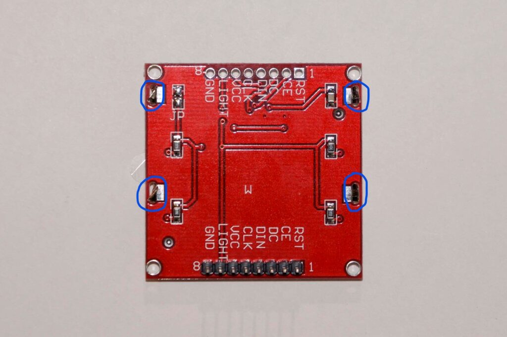
For modules that don’t respond to being squeezed, or to make a more permanent fix, it’s quite easy to remove the module from the PCB by loosening the four tabs at the sides (circled below):
This allows the display to be lifted away from the PCB. My two dud modules have different types of connectors on the back of the display. The first has old-fashioned spring metal contacts, with soldered pads on the PCB:

Pushing the contact block towards the display body in the direction of the arrow above, then reassembling and tightening the tabs by twisting them a bit gave me a (sort of) working display module. This module only displays text/graphics on the top half of the LCD, so unfortunately there seems to be an underlying issue and it’s still not much use.
The other display has some sort of encapsulated contacts to match up with unsoldered pads on the PCB:

With this one there was nothing to move/straighten on the LCD display, so I just reassembled, tightening the tabs by twisting. Once again this gave me a working display – in fact a fully working one this time. The best contrast setting for this module appears to be about 23.
So from five apparently duff display modules, it looks like 4½ are actually working. Realistically, call it 4! That’s certainly a lot more respectable than where I started out and suggests that a decent proportion of these displays do actually work.
Photogate Code Update
Once the display is working using the test program it should be simple to get it working in the photogate code.
The three highlighted lines below should be added to the photogate sketch’s setup routine, with the green highlighted number replaced with the best contrast setting for the display module that’s being used:

All things being equal when the updated code is then compiled and loaded onto the Uno board the result should be a working display for the photogate unit.
One thought on “Making Sense of the Nokia 5110 Display”