A few years ago I needed to generate a small and controllable amount of smoke for a shot I was working on: not too much smoke, as the subject was small. Now you can buy a big smoke machine like these foggers for not a lot of money, but the trouble is machines like this are designed for filling rooms. If your subject is small the shot is going to look like something out of a Victorian London murder story after about a quarter of a second.
My solution at the time was a hacked together contraption using the clearomiser unit from an e-cigarette, some aqarium tubing and a pump designed for inflating an airbed. The completed smoke machine was cheap to put together and did the job it was desgned for. But it wasn’t pretty, it was very fragile and the pump sounded like a tractor.
So where can you find a mini smoke machine that’s reasonably portable and, hopefully, reasonably priced? Good question. There is the MicroFogger 3 Lite, but at $140 plus shipping to the UK it’s not quite as reasonably priced as I was hoping for. The only other devices I’ve seen are the JPv Mini Fogger and the Tiny FX Smoke Generator. At $800 and about £800 respectively they take the price question to a whole new level.
Making My Own
Apart from those I haven’t seen anything that comes close to fitting the bill anywhere, so once again it’s time to build one. This time it’s got to be quieter, more robust and a lot more professional looking than my previous effort.
The starting point is once again a vape unit. For quietness and reduced vibration I originally considered using a fan to provide the airflow. However, after some tests and a bit of research it became pretty clear that a small fan can’t generate enough pressure to force air through the vape unit. As a result air flow is provided by a small (and reasonably quiet) air pump. Power is from a lithium ion battery rather than the four D-cells used last time around.
Given that the smoke machine is based on the heating element for a vape unit it shouldn’t run for long periods, so I included a timer circuit to switch it off after a sensible length of time. I’ve also added a key fob remote control to make it easy to fire up without fumbling about looking for the start button when it’s been carefully aligned for a shot.
Parts List
- Vape tank – Innokin Prism T18E (UK Link)
- 510 connector – Fat Daddy Vapes 510 v4 Connector
- 18650 battery
- 18650 battery holder
- On/off switch
- Air pump
- Remote control fob/receiver
- ICM7555 timer
- Resistors: 1kΩ (x2), 10kΩ and 75kΩ
- Capacitors: 10nF, 100µF and 220µF
- General purpose npn transistor (BC109)
- 1N4148 or 1N914 (or equivalent) signal diode
- Vero strip board
- Arduino single relay module
- P600D rectifier diode
- Li-ion charger module
- O-rings: 17 x 2.5mm and 22mm x 2mm
- Black PETG filament
- 1/4″ 20 heat set threaded insert
Vape Tank
First up, the vape tank: I did a bit of reseach on some vaping sites and learned a whole new vocabulary in the process. I ended up buying an Innokin Prism T18E vape tank. There are hundreds of vape tanks out there, but the key points for choosing this unit were:
- It is a top fill design (which means it can be filled without removing it from the body of the smoke machine),
- It has a 510 type power connector (which should make it easy to get a decent power connection),
- The glass sleeve isn’t completely exposed (which should make it less prone to getting broken).
Mounting the tank and providing power involves screwing it into the mating part of a 510 connector. Being no expert on 510 connectors, I decided the best thing to do was to buy one – in this case a Fat Daddy V4. Using an off the shelf connector ensures that the electrical connections will be solid. This only leaves the issue of designing a sealed pressure chamber to force pumped air through the tank.
Powering It
Referring to a voltage/resistance chart for vape heating elements, since the heater coil has a resistance of 1.8Ω the ideal voltage for powering it should be in the range 3V to 3.4V. This is a bit lower than the approximately 4.2 volts delivered at full charge by the 18650 battery I was planning to use to power the unit (or even the 3.7V nominal for the battery).
To address this I included a high power rectifier diode in series the the vape heating element to drop the voltage to a safer level. I used a P600D diode, as the current through the coil is going to be a little under 2 Amps and the P600D was the only recifier diode I had in stock that could handle over 1A of forward current. The forward voltage drop for the P600D is 0.9 to 1.0V, which lowers the voltage across the coil to 3.2 to 3.3V at full battery charge.
Electronics
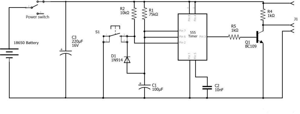
Timer
The timing circuit is a 555 timer in monostable mode. Looking at datasheets for the 555, depending on which version you have its minimum Vcc is 4.5 volts. The 555’s I had in my component drawer were a fairly generic 555P type, so it was questionable whether they would work from a 3.7 to 4.2 volts supplied by the 18650 battery. However, it’s been reported that 555 timers can work with significantly lower voltages than the datasheets suggest, so I built up the monostable on breadboard to check it out.
The circuit, powered by a pair of AA batteries (3.0 volts) worked fine, although the pulse length appeared to be a bit longer than the formula (below) suggests. As a result I decided use a CMOS version for the final circuit – the one I’ve used being an ICM7555. This is a pin for pin replacement for the standard 555, but uses less power and is guaranteed to run reliably off a 3 volt supply.
I decided that a blast of smoke of something approaching 10 seconds would probably be about right, but it would be useful to be able to extend this by pressing the start button again. This means the monostable has to be retriggerable, which adds some complexity to the circuit (in the form of a diode). Apart from the timer chip and the timing resistor/capacitor only three other components were needed, a pull-up restistor on the trigger input, a capacitor on the control voltage pin (pin 5) and a diode.
The formula for working out the pulse length (t) for a 555 monostable is:
t = 1.1 x R1 x C1
So for a 8.25 second pulse, with a capacitor value of 100µF, this gives a resistor value of 75kΩ.
Relay
The output from the 555 timer (pin 3) is used as the input to a relay module, which isn’t included in the diagram below. I used a relay module because I have loads of them that I bought for Arduino-based projects but have ended up using various solid-state switching circuits because I needed accurate timing. Timing isn’t such an issue for this project, as nobody’s going to be too worried if there’s a delay of a few milliseconds (or tens of milliseconds) before the smoke starts, so using a relay is fine.
However, just to make things a little more complicated, all my relay modules had an active low trigger input, while the 555 timer generates an active high output. The solution was to add a simple inverter circuit to the output of the 555. The npn transistor and two 1kΩ resistors turn the active high into active low to drive the relay circuit correctly. J1 in the diagram below is the connections to the relay module. Using an active high input relay module would mean that it can be driven straight from the output of the 555 timer, saving 3 components!
After successfully testing the timer and relay circuit using a momentary push to make switch, as shown in the circuit diagram above, the switch was replaced with the receiver of the remote fob in the parts list above. This just requires connections to Vcc and ground to power it, with the receiver’s other two wires connected in place of the switch S1 in the circuit diagram.
Once the circuit was working on breadboard, it was built it up on vero stripboard. At this point I added a 220µF capacitor across the circuit’s supply to smooth any spikes when the power switch is turned on.
Circuit Diagram
The Enclosure
The timer/heating element control part of this project were built and tested months ago, but the enclosure design has been a real challenge and has gone through several iterations in an attempt to get decent airflow through the vape unit and still make everything fit in a reasonably sized package.
Pressure Block
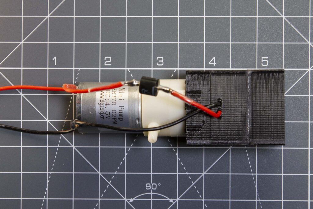
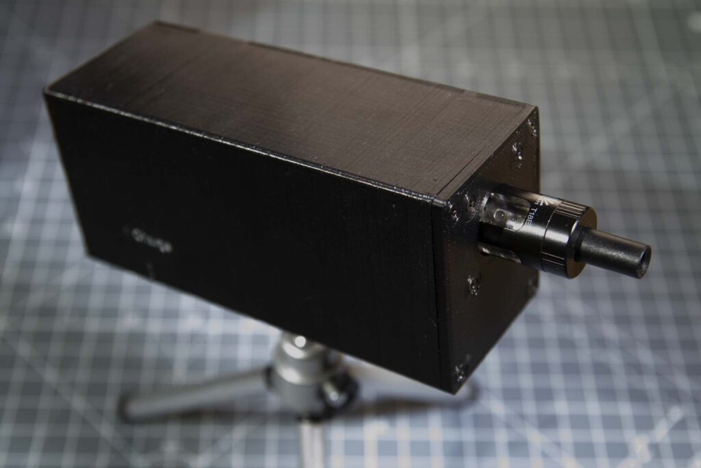
It’s a very grand sounding name, but it is a block that’s under some pressure. The pressurised part of the smoke generator comprises a mount for the vape tank with a mount for the pump behind it. This pushes air from the pump’s output round the 510 connector and through the vape tank, making smoke.
The tank mount is designed to be printed in two parts to avoid having to print with supports in one of the o-ring grooves. This should make the grooves less rough and hopefully give better seals. It also makes it a lot easier to mount the 510 connector, as this can be done before the two parts are glued together.
The mounting for the vape tank and the pump mount were 3D printed using black SunLu PETG filament. I used PETG for the parts in case things get a bit warm around the vape tank and pump: PETG has better heat restistance properties than PLA. Parts were printed at standard (0.2mm) layer height, with a nozzle tempartature of 245°C and bed temperature at 80°C.
Assembly
After printing the two-part tank mount, the 510 connector (with flying leads) was fixed on the front part and the back was glued in place using J-B Weld epoxy. Before glueing I inserted lengths of 1.5mm brass rod into the holes in the adjoining faces to ensure good alignment and provide extra strength in the join. The flying leads from the 510 connector exit through the two holes in the back part of the tank mount.
The pump mount was bolted to the tank mount using M2.5 bolts, ensuring the 22mm x 2mm o-ring was located in the grooves on the back face of the tank mount. The pump is a push fit in the back of the mount, but I added some silicon sealant around the join, and round the vape leads, after it had been tested. The assembled unit, with pump in place, is shown below:
Case
As well as holding the pressure block, the case needed to contain the battery, control board, remote board, relay module, battery charge module and the on/off switch. All this and a tripod mount, and all in a package that was as compact as possible. So not much to that then!
The front part of the case is just a flat plate, with o-ring seal, that bolts on to the front of the tank mount. This completes the seal round the vape tank. The back case is again just a flate plate, but this time with mounts for the relay module on the inside. The sleeve that the case ends bolt to has mounts for the power switch and the battery charge module, and a hole in the base for a 1/4″ 20 heat set insert for tripod mounting the unit.
The case’s front, back and sleeve were printed in black PETG at the same temperature as the earlier parts. Since the front and back are both quite thin they were printed without the usual coating of glue stick on the printer’s build plate. The sleeve was printed back end down with supports and with a brim, as it’s quite tall for its footprint on the build plate.
Assembly
Front Plate
The vape tank was screwed into the 510 connector in the pressure block. The front plate was then bolted to the front of the pressure block with four M2.5 bolts, ensuring the 17 x 2.5mm o-ring was in place around the base of the vape tank.
Back Plate
The relay module was bolted to the mounts in the back plate, relay end towards the bottom, using four short M2 bolts.
Sleeve
After printing and cleanup/support removal the first step was to add the 1/4″ 20 heat set insert into the hole in the base for mounting the unit on a tripod. As usual the insert was heated up with a soldering iron and pushed most of the way in, then finished by pushing the base of the sleeve down on a flat surface.
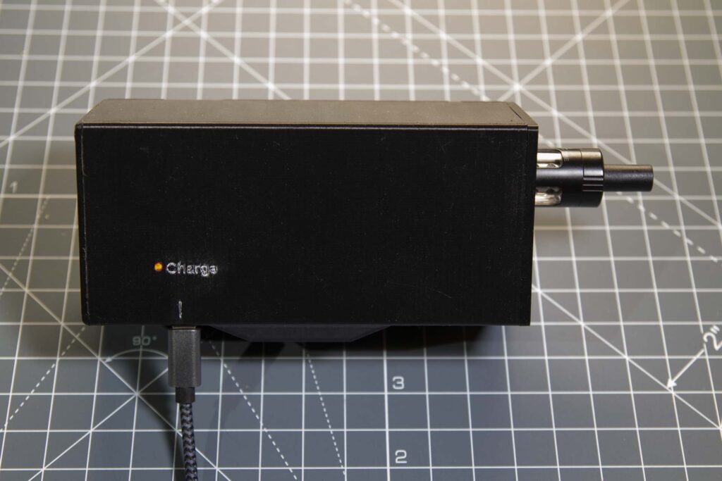
Next came the slightly fiddly bit – mounting the battery charge board. I’ve found the USB connectors on these boards to be very easy to break, so before fitting it in the sleeve I strengthened the bond between connector and board using 5-minute epoxy. The bottom air slot on the side of the sleeve has been aligned so that when the charging board is in position a thin-shafted screwdriver can screw in the two M1.5 bolts that hold it. A very small (2mm long) piece of 2mm diameter acetate rod was glued into the hole behind the charging board. This allows the battery charge status to be viewed – red for charging, blue for fully charged.
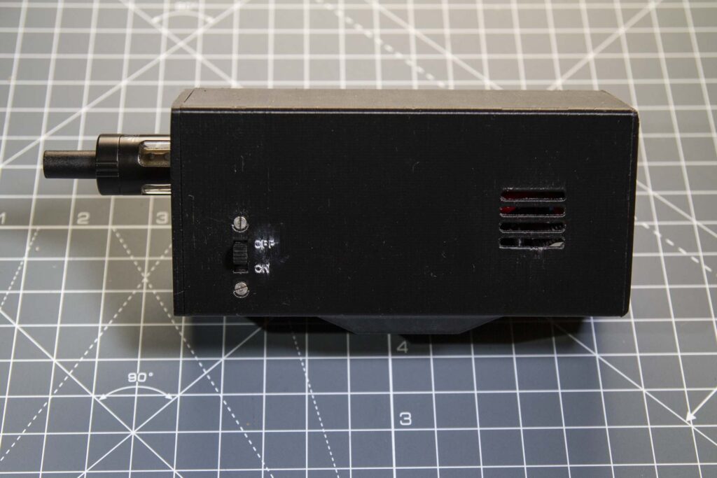
The other component that had to be attached to the case sleeve was the on/off switch. The switch is a bit bigger than I really wanted, so to get it to fit the top contacts were cut off (only the middle and bottom contacts were needed). Flying leads were soldered to the middle and bottom contacts and the switch bolted into the sleeve using a pair of countersunk M2 bolts. The switch has a quoted maximum current of 0.5A at 50V, so it shouldn’t have a problem handling the ~2A at 4V that flows through the heating coil and pump.
Wiring It Up
To save space I used an 18650 battery holder rather than design and print my own as part of the case. I wouldn’t use one of these if the battery had to be taken out to charge as removing the battery from these holders is pretty hard work. However, since I’ve built in a USB battery charger circuit the battery should be a permanent fixture. The battery holder was glued to the bottom of the pressure block using 5-minute epoxy.
Before doing the final assembly I did a functional test with the main parts, excluding the charge board, connected up with test leads:
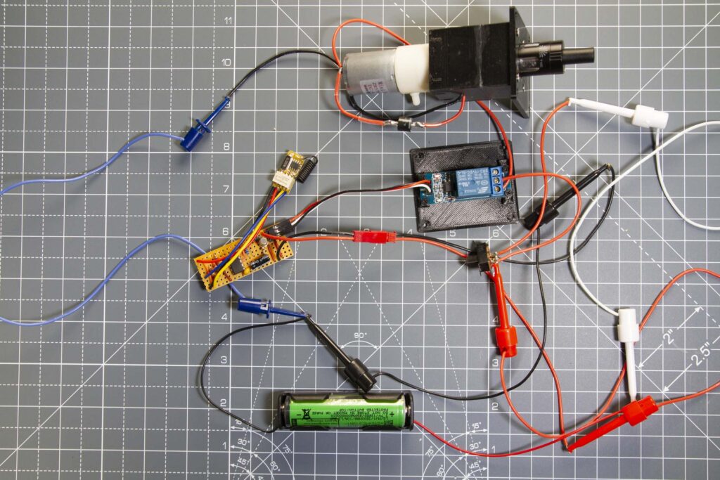
That all seemed to go OK, so I took it apart and reconnected with the components in the case. All the electronic parts had flying leads attached before the unit was assembled – these were shortened and had connectors attached as necessary when they were in place. After closing it up the completed unit looks like this:
And when it’s charging (the light turns blue when it’s fully charged:
In Use
Being a bit paranoid about using hot parts predominantly surrounded in plastic, I’ve done a lot of testing to see if there are likely to be any heat problems with the unit. So far I haven’t felt the outside of the vape tank even getting much more than warm-ish. This does not constitute a guarantee, however, and anyone who replicates this design does so at their own risk! The stereolithography files for the enclosure can be downloaded here.
And does it make smoke? Here’s a shot of the unit in doing its thing (shutter speed 1/5 second, so not exactly freezing the action):
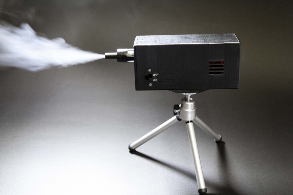
As you can see the smoke machine works well, giving me exactly what I set out to produce. I think I could have made it a bit more compact if I’d used a smaller battery and the lower-flow version of the pump. It would also have been good be able to use a slightly bigger vape tank, but capacity is limited to 2ml in the UK so that’s as big as I could get.
A note on smoke juice
It is possible make your own using a glycerine and distilled water mixture (25% to 75% ratio). I made some of this up for testing the unit, but it produced a pretty feeble fog that was far thinner than I was looking for. I’m currently using commercially available medium density smoke juice: this creates a much higher density fog that disperses more slowly.