One of the surprises from the testing for my post on LED light quality was the spectrum produced by my generic 3W SMT COB LEDs. While not as good as the 95 CRI Nichia LEDs they looked pretty decent considering they cost about 50p each. Another thing in their favour is that they run off a voltage of 3.2 to 3.4 volts. So while my high CRI Nichia COB LEDs may produce a fantastic quality of light, their requirement for a supply voltage of about 35V doesn’t make them particularly easy to incorporate in a small, battery powered light source.
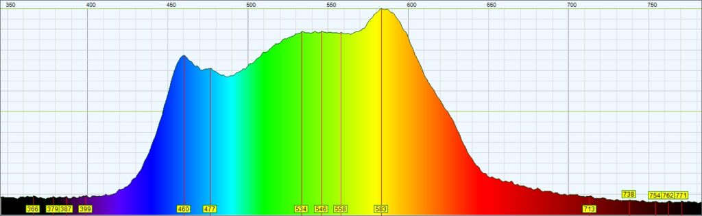
The main shortcoming of the 3W LEDs appears to be the sharp fall off in their spectrum above yellow wavelengths. Compared to the Nichia 95 CRI LEDs there is a lack of red in the light they produce (spectrum for 3W LED below).
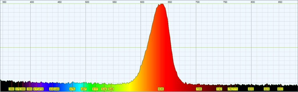
This got me thinking: what does the spectrum from a similar 3W “warm white” LED look like. And how about augmenting the spectrum of the completed light by including some 3W red LEDs? To find out, I splashed out on ten warm white and ten red LEDs in the same SMT packaging. The first thing I did when they arrived was check out the spectra they produce: these are shown below – no prizes for guessing which is which!
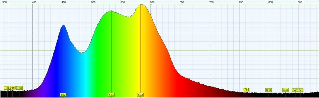
I was a bit disappointed with the warm white LEDs as they didn’t have a very good response in the cyan region and, disappointingly, had no significant extension in the red region compared to the daylight version.
Note that when you look on eBay and the like for these type of LEDs, 3W ones with this packaging appear to come in at two very different price points: mine cost about £5 for ten. There are others that you can get 100 for just over £7 – I haven’t tested these, but suspect they might not do quite so well.
Objective
Now I had a fair collection of 3W LEDs, and based on the light intensity I measured with a single daylight LED (see my post on light power), with ten of the daylight LEDs combined with a couple of warm white ones, depending on how hard they’re driven the output should be at least 2,000 lumens of light. That should be equivanent to the best part of 200W of tungsten lighting. While that wouldn’t cut it as a main light it would make a reasonably useful fill light or source for light painting. To try to get more energy up in the red band, I also decided to add a couple of red LEDs into the mix.
As far as the physical form of the light was concerned I planned to mount the LEDs in a line inside some sort tube that’s translucent on one aspect (I would say ‘side’ but it’s a round tube). Fit batteries, on/off switch and dimmer, and Bob’s your uncle: a DIY pipe light. It’s a cheap and cheerfulhome-build alternative to a very popular, and expensive, strip light (or Ice Light, to give it a name) which unfortunately there’s no way I can afford.
Parts
- 10x 3W SMT COB daylight balanced white LED
- 2x 3W SMT COB red LED
- 2x 3W SMT COB warm white LED
- LED driver board ( Maxic MT7282 based)
- Double sided thermal tape
- Two 18650 batteries
- Battery contact pair
- On/off slider switch
- Rotary potentiometer – 10kΩ logarithmic
- Anodised alloy knob for the potentiometer
- Resistors – 3kΩ and 47kΩ
- Black tube (32mm FloPlast PP polypropylene pipe)
- Straight pipe connector, 1″ PVC
- Straight 1″ PVC to 1″ screw BSP adapter
- 1″ PVC BSP screw cap
- Push-on cap, 1″ PVC
- Aluminium heat resistant tape
- Frosted window material
- 21.5mm plastic overflow pipe
A quick note about pipe and the bizarre unit change that appears to have happened in the parts list. I bought a length of black 32mm FloPlast PP waste pipe at my local DIY store because it actually looked quite good for what I was trying to achieve here. The selection of fittings in this size, and in black, was very limited so I decided to source them online.
However, when I measured the dimensions of the pipe, I found the outside diameter was 34.5mm and the inside diameter 30mm – so much for 32mm! Looking online – at www.plasticpipeshop.co.uk – I found the closest I could get to the 34.5mm outside diameter of my polypropylene pipe was 1″ push fit PVC pipe fittings, which have an interal diameter of 33.6mm. I probably should have bought 1″ pipe online as well, but decided to bash on using the 32mm(!) pipe I already had.
Preparation
Before trying to construct a suitable housing for the light, the first problem that needed to be solved was working out how to drive the LEDs. I wanted to make the light dimmable, but running the best part of 30 watts of LEDs from a low voltage battery, with dimming, presents a few challenges. Mercifully with the rise in popularity of LED strings in the likes of automotive applications, where everything has to run off a low voltage, the semiconductor industry has been getting quite creative in this area and there are a whole raft of boost LED driver chips on the market. These can be powered by as little as the voltage from a single cell, can drive single or multiple strings of quite high intensity LEDs with a constant current (which is what LEDs like), and mostly have dimming capability thrown in.
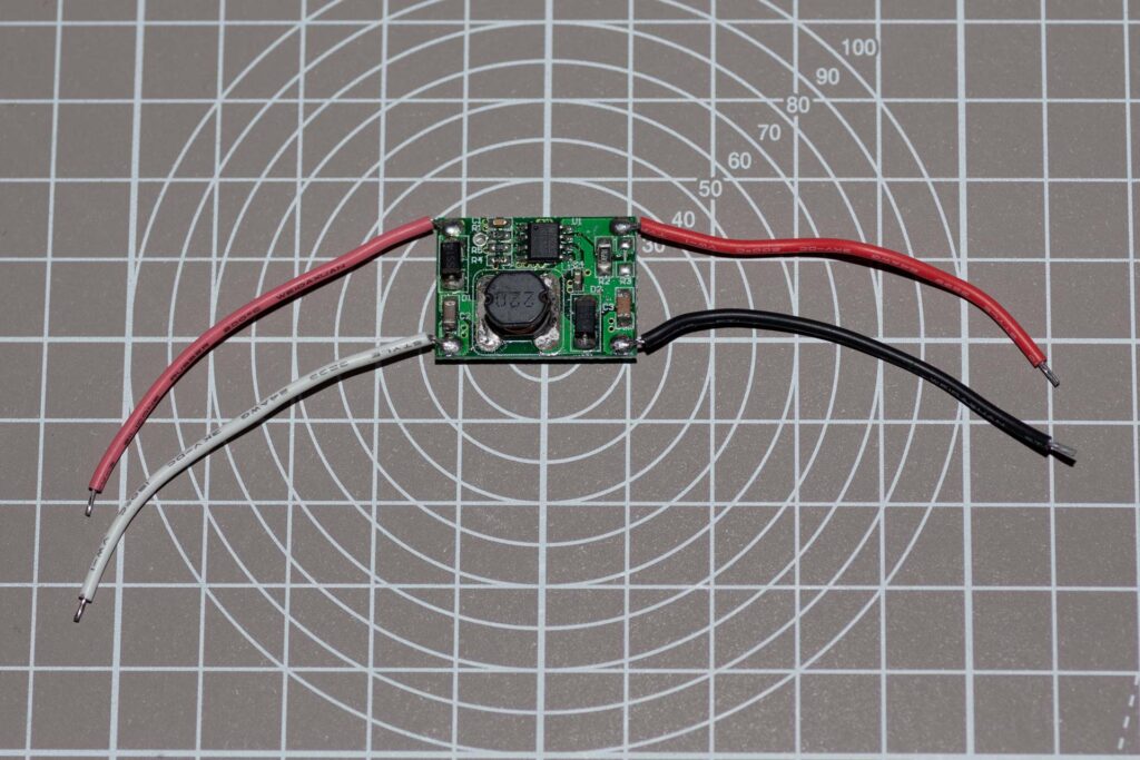
After looking through the datasheets for a load of boost LED driver chips, for this build I decided to use the Maxic MT7282. This can drive a string of up to 10 LEDs at 350mA (which is not exactly hammering them), and has current dimming built in. Even better, you can buy a module that uses the MT7282 on ebay for just over £1. I’d imagine that’s cheaper than I could buy the components, and also saves trying to hand-solder surface mount chips. Win-win you could say: I bought several. The data on the module says it can drive from 3 to 7 LEDs connected in series, so I’ve used two of them, each driving a string of 7 LEDs.
Building It
With the question of the LED driver out of the way it was time to put the housing together. First, opening up the inside diameter of the PVC parts so they would fit the 32mm pipe. This took about 10 minutes of working around the pipe socket for each fitting using a Dremel with sanding band attachment. The fittings were sanded out until the pipe was a reasonably tight push fit. The plastic grit produced by sanding PVC fittings gets everywhere so don’t do this in your kitchen, and wash the parts with soapy water when you’re done to remove any residual grit.
Battery Holder
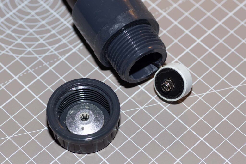
Working out how to build the battery holder I discovered that by an amazing piece of luck, an 18650 battery is a slide fit in a piece of 21.5mm outside diameter plastic overflow pipe (the lighter duty version with an inside diameter of about 19mm). To make the battery holder I cut a 150mm length of this pipe using a pipe cutter and drilled regularly spaced holes down the sides just in case the tube was going to insulate so well it would make the batteries run hot. At one end I fixed a blanking plug with one of the positive battery terminals glued to it. The plug is about 5mm thick: it was drilled and tapped with an M2 hole on each side and was bolted into the end of the battery tube, with a bit of hot glue added to stop it rotating on the bolts and potentially becoming misaligned. That was the easy end!
The other end of the battery tube is left open but needs a contact that will be pushed against the negative end of the second battery, but won’t rotate as the end cap is screwed on to compress it as it has the negative wire attached. This turned out to be a pretty challenging proposition and when the light was put together the first design proved to be a complete failure.
Design number two for the negative battery terminal comprises a short (about 7mm) length of overflow pipe with a negative battery terminal sandwiched between two 3mm thick layers of styrene laminated from 0.5mm sheet. The negative lead is soldered to the battery terminal’s tag, which prodrudes from a slot cut in the side. This allows it to drop out of the way for battery removal/insertion when the end cap is taken off the handle. It would have been better to have the spring contact fixed into the end cap, but since cap and tube are all plastic that wasn’t very practical as there’s no conductive path to the rest of the electronics.
The ‘handle’ tube of the light is a length of 32mm pipe that fits into a straight to BSP screw adapter at one end and a straight coupler at the other. My battery holder was about 150mm long, so given it needed to protrude into the straight to BSP screw adapter, the tube for the handle didn’t need to be particularly long. However, to give enough space to fit the sliding on/off switch before the straight coupler I used a 175mm piece of pipe. A slot and fixing holes for the light’s on/off switch were cut in the tube just before the straight coupler.
Before fitting the straight to screw BSP adapter I removed the hexagonal flats from it with a file – this would have been a lot easier and given much better results using a lathe, but I had to make do with the slightly rough and ready results you get with a file. It took quite a while, but with a lot of perseverence I eventually got it looking reasonably respectable. I also cut a slot on the inside to allow the negative battery wire to get through without being squeezed.
The screw-on cap at the end of the handle has to be removable to take out the batteries for charging, but is also the light’s tripod mount. Tapping a 1/4″ 20 tpi tread into fairly thin plastic isn’t going to produce the most durable result, so to ensure it was strong enough the end cap was reinforced with the top plate of a cheap £1 tripod that already had a 1/4″ 20 thread. This was filed down so it fitted inside the centre of the cap and still allowed it to fully screw on to the straight to BSP adapter. The plate and end cap were drilled either side of the 1/4″ 20 hole, and the holes in the plate were tapped with an M2 thread so it could be screwed into the cap to stop it rotating.
Housing the LEDs
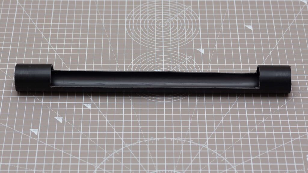
The business end of the light is another piece of PP pipe, this time about 340mm long (about 20mm of this disappears into the fittings at either end, giving a visible length of about 300mm). When the pipe was cut, half of it had to be removed for about 250mm of its length to allow the light to get out. This was done by cutting a slot half the pipe’s diameter about 40mm from each end, then adding masking tape guides between the slots on each side and cutting along these using a Dremel with circular saw blade attachment. This took a fairly steady hand, and like working on the PVC fittings it generated a lot of nasty grit/swarf that went everywhere. When it was done I took a sander to the cutout to smooth out the irregularities in the Dremel cut. As ever after these type of plastic cutting and sanding operations, the pipe was given a wash with soap and water when it was finished to remove all the dust and swarf. The result looked like this:
Once it was clean the inside was lined with aluminium heat protection tape, not really for its heat resistant qualities, but to ensure that any stray light inside the unit was bounced straight back out again.
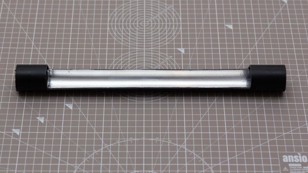
When I did the spectrum test with them running on 3 volts, the 3W LEDs didn’t appear to generate too much heat. However, when they are cranked up a bit they do get reasonably warm. There is a round metal plate on the back of each LED which suggests that it would be a good idea to mount them on something thermally conductive. For this I used 6mm square alloy bar: this was drilled and tapped through the ends and bolted into the back of the tube on top of the aluminium tape. I think between the bar and aluminium tape excess heat build-up should be avoided and the LEDs should stay at a comfortable working temperature.
A note on tapping holes in metal: while you can get away with a lot tapping holes in plastic, metal is, not surprisingly, a slightly tougher prospect. I was using an M2 tap, which should have a clearance hole of 1.6mm. Since that’s not a standard size for most drill sets it is possible to get away with using 1.5mm, but with a tap as small as 2mm you have to take a lot of care to ensure you don’t shear it, as even with a small tapping wrench you can exert a lot more torque than the tap will be able to withstand. Therefore reverse frequently to clear the threads and use a cutting lubricant, such as Rocol RTD, to make the tap’s life a bit easier.
My aim was to stick the LEDs to the bar at roughly 18mm intervals, attaching them with small pieces of double sided heat conducting tape. However positioning them is quite a fiddly job and the first batch of seven are a bit close together, so the second batch are spaced a little wider. In the grand scheme of things I don’t think this is going to matter too much. Having the LEDs fixed to the bar made it pretty easy to solder the connecting wires to them. The LEDs are connected in series in two groups of seven, so they are arranged with alternate anodes and cathodes on each side to make the wiring simple – see the photo below if that’s not the clearest description:
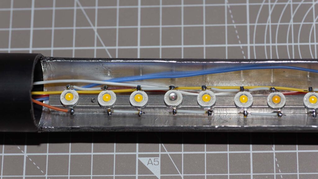
A driver board was attached to each of the strings and tested with a bench supply set at about 7.5 volts, which is roughly what the two 18650 batteries will supply. Other than one duff LED (one of the warm white ones), everything worked fine.
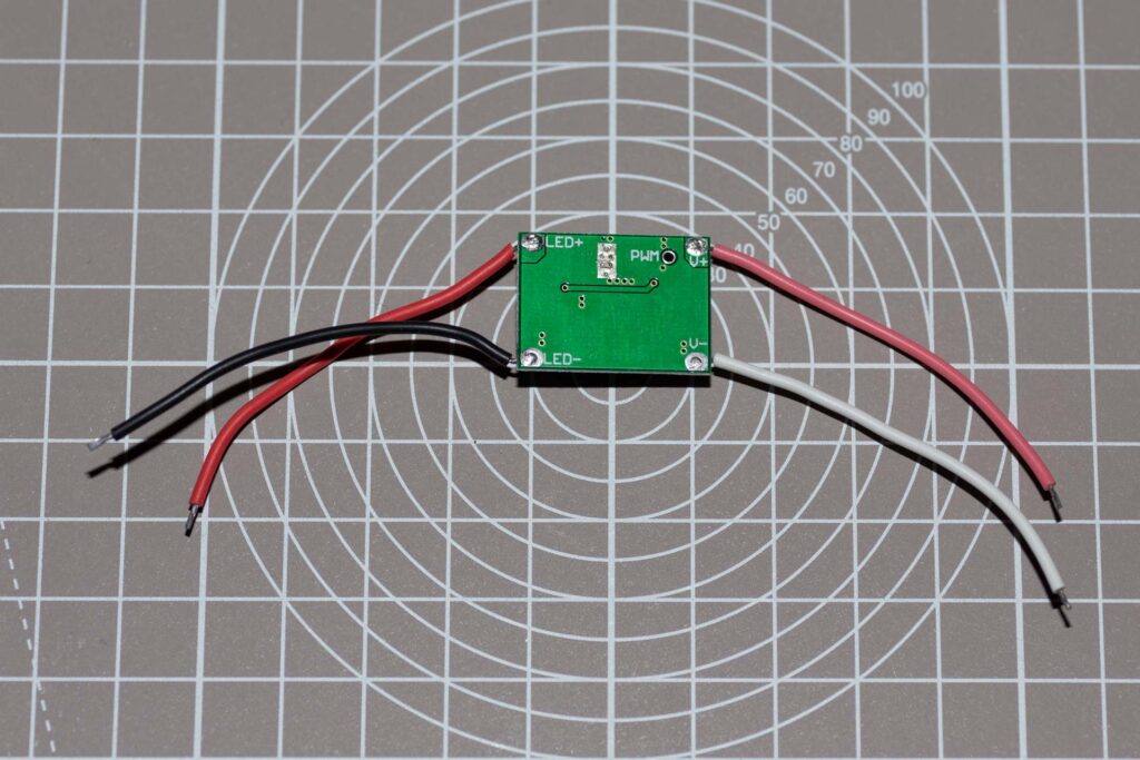
Controlling Light Output
To provideLED string dimming, there’s a contact point on the driver board (see photo above) where you can apply either a PWM signal or a voltage. If the signal at this point is between 2 and 5 volts the driver chip will be expecting a PWM signal. However, if the voltage is between 0.4 and 1.6 volts the driver will dim the LEDs based on the voltage (1.6V for max brightness). To provide this voltage I used a 10kΩ potentiometer, with a 47kΩ resistor from the high end of the pot to battery positive, and a 3kΩ resistor from the low end of the pot to battery negative. This gives a range of 0.38V to 1.64V, on the chip’s ‘ADJ’ pin, which works just fine. The technical details for the driver module (and labelling on the back of the pcb) only mention the PWM dimming option and not the voltage dimming option, but the Maxic MT7282 datasheet makes it all a bit clearer.
With all the electronics tested it was just a case of drilling a hole in the end plug to mount the potentiometer and doing the final wiring: battery positive to the on/off switch; other side of the switch and battery negative to both driver boards and the restistors connected to the dimming potentiometer; potentiometer’s wiper (middle pin) to the PWM points on the driver boards and driver board outputs to the two strings of LEDs. I’m not a great fan of hot glue as a medium for holding pcb’s in place, but on this occasion with small rectangular pcb’s in a small round tube I had to compromise, so hot glue it was. I also used a few more blobs of hot glue to keep the wiring alongside the LEDs tidy.
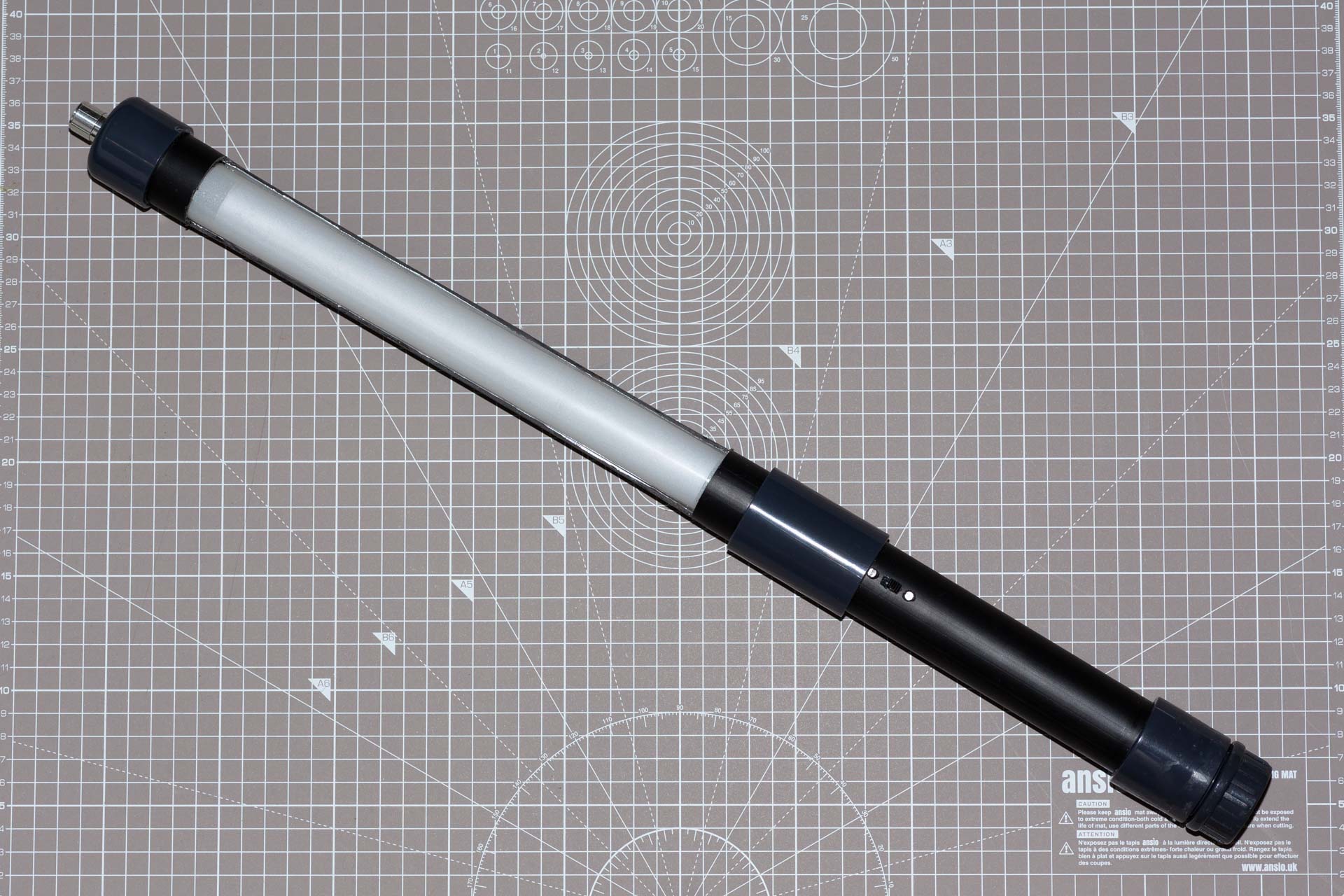
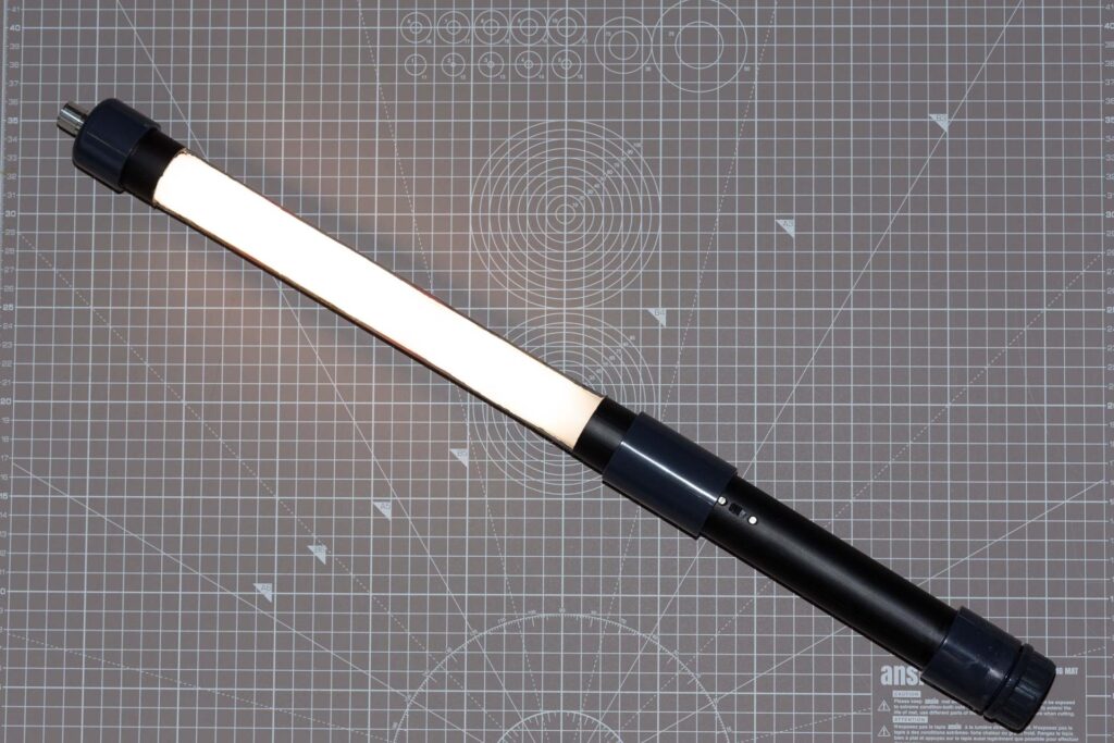
And finally, the diffusion material was added to the cutout in front of the LEDs. This comprises a couple of layers of diffuser from a dissassembled laptop screen, with a layer of frosted window diffusing material stuck to them. The end result looks like this:

Testing
Since every other light source I’ve switched on recently has had my spectrometer pointed at it, I couldn’t make an exception for this one. The spectrum it produces is shown below:
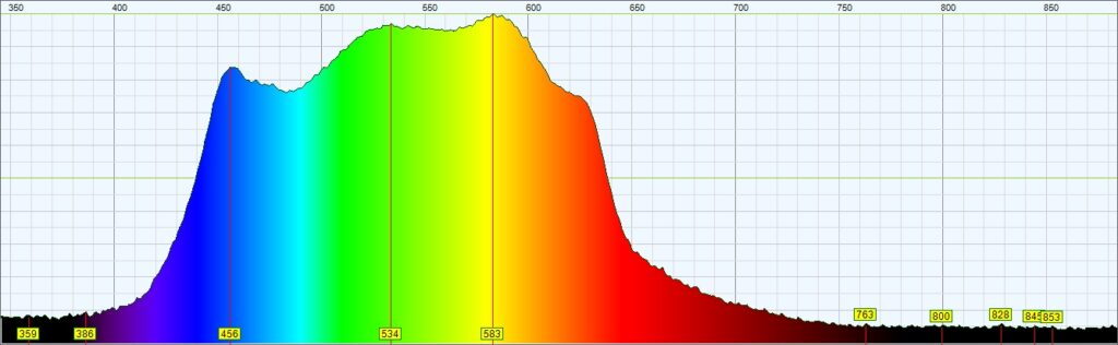
To me it looks like it was definitely worth adding the two red LEDs for the extended response at the red end. And what about light intensity? Taking a look at the spec for the Westcott Ice Light 2, the quoted light output at 1m is 522 Lux. Doing the same measurement for this light at maximum brightness gives a reading of 220 Lux at 1m. So less than half the intensity of the Westcott, but at a lot less than half the cost.
With higher current driver modules to make the LEDs work a bit harder it should be possible to produce quite a lot more light from this setup if you feel that the output is too puny. However, since this was just an experiment using about a fiver’s worth of LEDs to make a light, I’m happy with 220 Lux.
Overall I think the light looks ok, but I can’t escape the conclusion that it’s basically plastic waste pipe and couplers, and to my eye the couplers are a big give-away visually.
While I was what seemed like endlessly filing the flats off the straight-to-BSP adapter my mind did drift to better ways of achieving this kind of build. Later in the project my mind did more than drift when I was struggling to put together a reliable negative contact mechanism for the battery holder – being ingenious with plastic pipe, springs and washers can only get you so far …
The first solution I came up with was getting set up with a lathe and milling machine and machining parts from solid. Alternatively, option two was buying a 3D printer and fabricating parts using that. I think the latter is likely to be a better fit for my budget. Time to do some research!
4 thoughts on “A DIY Pipe Light”