After the unbridled fun of building my pipe light a few months back it struck me that since the build was in part my justifcation for buying a 3D printer, it would be a good idea to revisit the project and do it better using 3D printed parts. Now that’s the sort of challenge that could cause a load of buyer’s remorse if the result isn’t better and the build time a lot shorter. Risky, but I decided to give it a go … The result – well it isn’t a pipe light any more because no pipe was used in its construction, so maybe a tubelight?
From an electronics perspective the basic design is the same as last year’s original: two sets of 3W LEDs connected in series, powered by constant current LED drivers with dimmer and all running from a pair of 18650 batteries. The MT7282-based boost LED drivers are the same as in the previous build, so with a maximum of 350mA drive current the LEDs aren’t being driven particularly hard, and therefore aren’t generating a lot of heat. As result I’ve spaced them closer together on the metal heatsink bar, so the light can be made a bit shorter overall.
This time I’m using six daylight balanced LEDs plus one red LED in each of the strings, as I’m not convinced that the addition of a warm-white LED in each of the strings last time round added much to the colour spectrum being produced.
Parts
- 12x 3W SMT COB daylight balanced white LED
- 2x 3W SMT COB red LED
- LED driver board (Maxic MT7282 based)
- Double sided thermal tape
- Two 18650 batteries
- Battery contact pair
- On/off slider switch
- Rotary potentiometer – 10kΩ logarithmic
- Anodised alloy knob
- Resistors – 3kΩ and 47kΩ
- Aluminium heat resistant tape
- Copper clad laminate board
- Length of ~1mm copper wire
- Small spring
- JST RCY plug and socket (2 pin)
- eSun PLA+ black printer filament
- Clear PETG printer filament
- 1/4″ 20 heat set threaded insert
Printing
The parts for the tubelight were all designed in Fusion 360 – there are eight components:
- Handle
- Cap
- Lower tube
- Upper tube
- Diffuser
- Driver board holder
- Battery disk
- Handle spacer ring
With the exception of the diffuser, driver board holder and handle spacer the printed parts were all made from black eSun PLA+ with 0.4mm nozzle and a standard quality 0.2mm layer height. Print settings were generally fairly standard, with a print temperature of 210°C and a bed temperature of 55° to 60°C. The driver board holder and handle spacer were printed from generic white PLA, as this was what I had loaded in the printer after I’d done a bit of maintenance work and fitted a new print nozzle. Settings for the white PLA were the same as for the other PLA parts.
The handle was printed threaded end to the build plate, with supports and a raft, as it’s a tall thin print and the raft gave it extra stability when the upper layers were being printed. The other two tube parts were also printed with rafts for stability, but didn’t need any supports.
The diffuser was printed with clear PETG – this was printed curved side down, with very sparse (10%) support. Print temperature was 235°C and bed temperature 70°C.
The amount of time spent filing plastic parts with this build was minimal – the tubular parts had to have a bit of stringing removed and the battery cavity was sanded to ensure there were no sharp lumps that might damage the batteries or make them stick, but that was about all.
Build
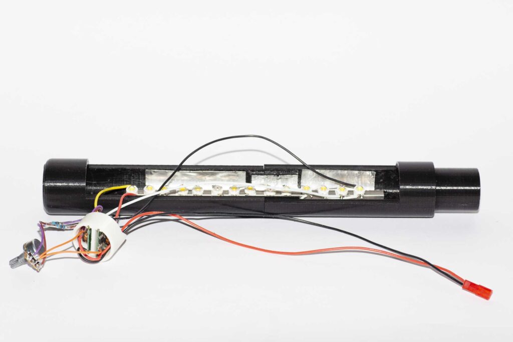
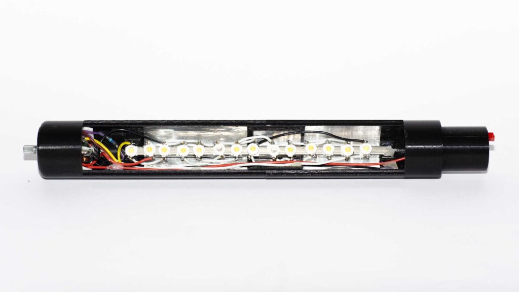
As before the LEDs were attached to a 6mm square alloy bar with double sided heat conducting tape and soldered together in series. In the original pipe light the two drivers dim at a slightly different rate, so as the brightness reduces one end of the LED array is noticably dimmer than the other. This time the two sets of LEDs were interleaved to avoid that problem. The LED spacing was also reduced as the driver only knocks out a maximum of 350mA, so the LEDs aren’t being driven too hard and there’s not too much heat to get rid of.
However, with all the extra wires in a confined space some of the LEDs tended to get pushed off their heat conducting tape, so I used a blob of 5 minute epoxy either side to keep them in place. Aluminium heat resistant tape was added to the inside of the two tube parts before assembly, primarily for its light reflection rather than heat proofing properties.
Light End
With the LEDs on the bar the drivers and top end wiring were put together. The 10kΩ pot had a pair of wires attached to the centre pin and one each to the end pins – there’s not a lot of space up in the top of the light, so I didn’t attach the resistors directly to the pot in case they got in the way of the driver holder. The pot was fixed through the hole at the top of the light and an alloy knob was added.
The rest of the wiring at the top end is: pot high side through 47kΩ resistor to battery positive; pot low side through 3kΩ resistor to battery negative; battery negative and positive to the correct pins on both driver boards; the LED strings to the LED pins on the driver boards and the two wires on the pot centre to the PWM pins on the driver boards.
That sounds simple, but it’s worth working out which wires want to go behind the driver holder prior to assembling it all, as there’s quite a lot going on in a pretty small space. Also note: it’s not obvious in the photos, but the resistors have clear heat shrink sleeve over them to avoid shorts. Finally the battery positive and negative wires were connected into a 2-pin JST RCY socket so that the top and handle sections of the light don’t have to be physically connected when it’s all being wired up.
When the wiring was complete the diffuser was put in place and the two parts of the tube fixed together with a countersunk 6mm M3 screw.
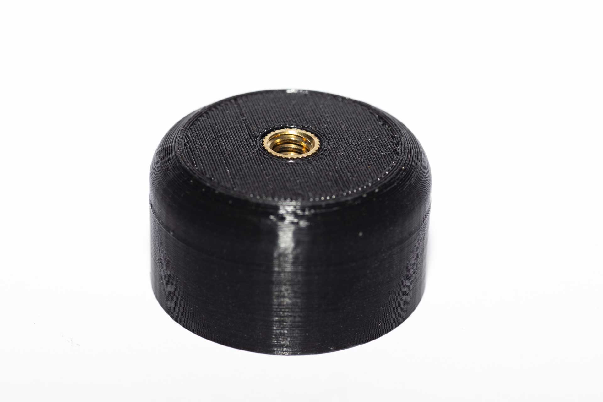
Handle
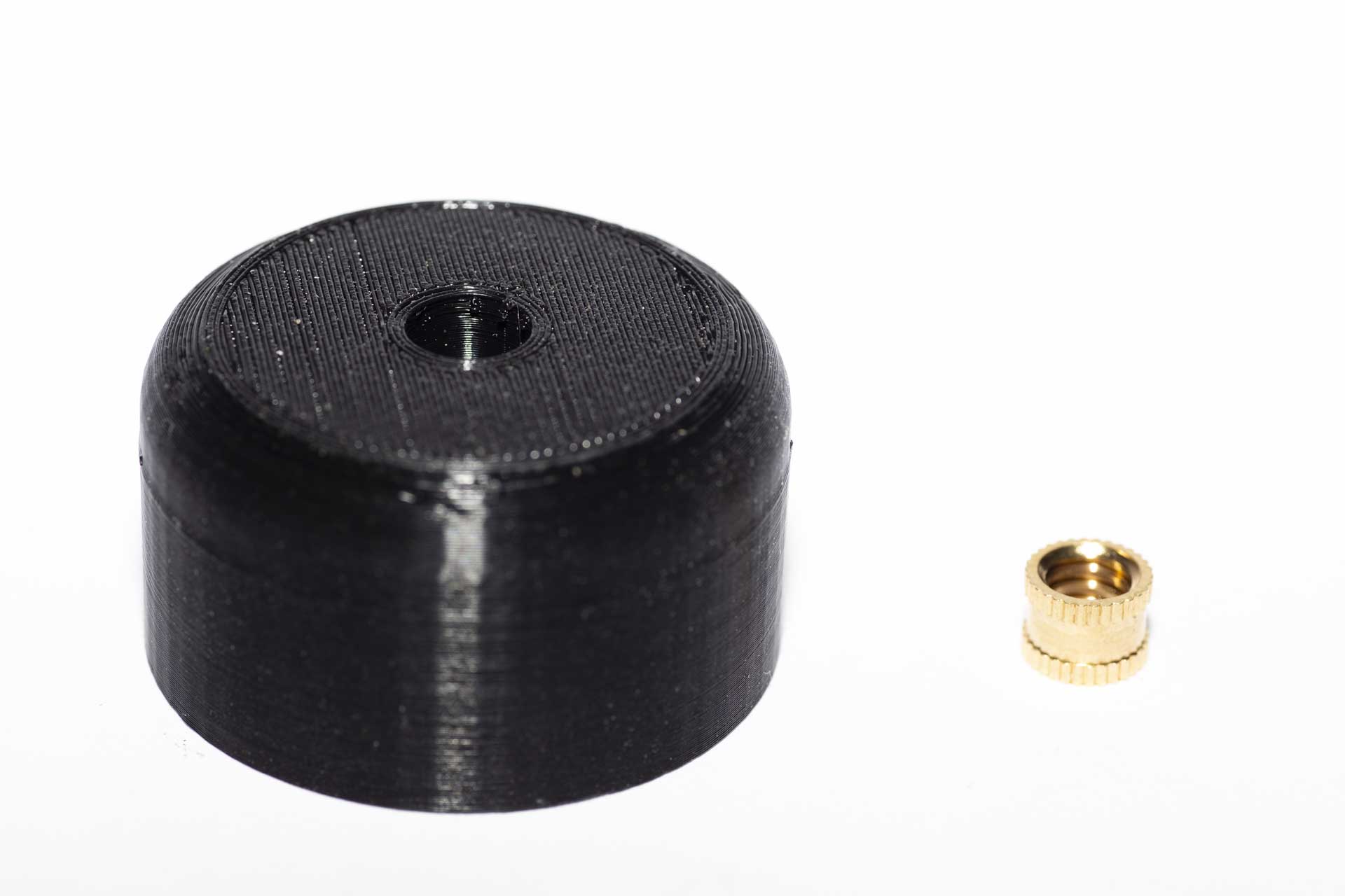
With the top end complete it was time to assemble the handle. Starting with the removable cap, this has a hole in it that’s designed to take a 1/4″ 20 thread per inch heat set brass insert – this should give a much stronger tripod mount than just threading the hole in the plastic. The insert was heated up with a soldering iron and pushed into the hole from the outside. I find these inserts go in fine if they’re heated with the soldering iron bit in the threaded hole, but for the last ~1mm I turned the cap over and finished it off by pushing it on the surface of the workbench – this ensured the insert was square and flush with the end of the cap.
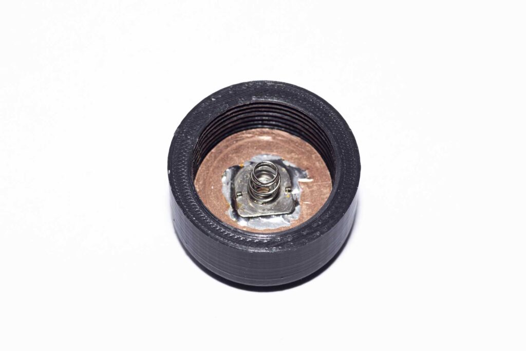
Once the insert was in place the contact was added to the inside of the cap. To make this I cut a circle of copper clad laminate pcb board with a 35mm hole saw, filed the edge a bit until it fitted in the cap and soldered a battery negative spring contact in the centre. This assembly was then glued into the cap with 5 minute epoxy.
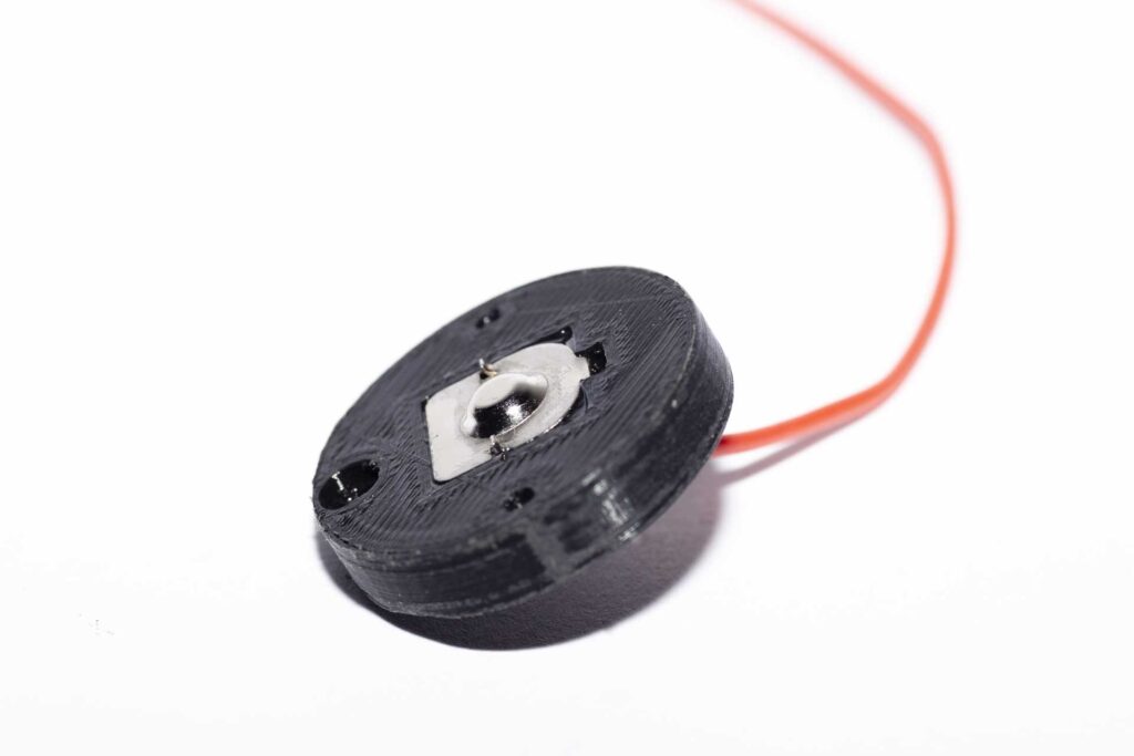
Moving to the other end of the batteries, a positve (flat plate) battery contact had the positive wire soldered to it and the solder tag bent to a right angle before being fed through the hole in the battery disk and glued in place, again using 5 minute epoxy.
The Fiddly Bit
Now the slightly tricky bit – the negative contact in the cap is connected through to the battery disk using a sprung copper contact rod that runs through a hole the length of the battery tube in the handle. The rod is a length of the earth wire from a twin and earth cable, and has the end of the negative lead wrapped round it and soldered on close to the top end to form a ridge: the battery lead then runs through a small coil spring before being pushed through the hole in the battery disk.
The copper wire was fed through the hole in the handle, making sure the spring fitted inside the couterbore at the top of the hole with some free movement, then the battery disk was screwed in place on top.
With that done the copper wire sticking out at the cap end was cut so it protruded by about 6mm, and the end rounded off with a needle file. This all went together as planned, and the protruding end can be pushed back so it’s flush with the end of the tube, springing back into place when it’s released. When the cap is screwed on this makes contact with the copper laminate board inside the cap, completing the negative side of the circuit.
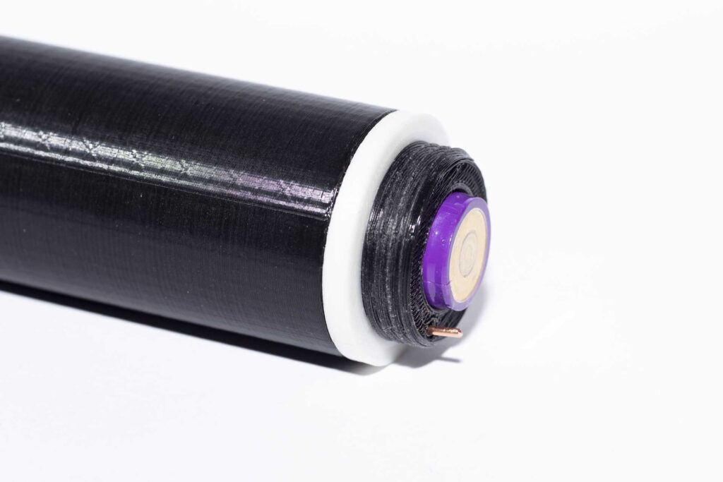
Making a Mistake into a Feature
What didn’t quite go to plan was that I got the length of the battery tube slightly wrong, so it’s about 4mm too short. Rather than reprint (it’s about an 8 hour print) and reassemble the handle for the first version I decided to make a feature of this and printed a white spacer ring that screws on to the handle ahead of the cap. To my mind this actually looks really good, so I decided to add the spacer ring file to the set of parts for the light rather than lengthening the handle.
Finishing off the handle, the positive battery wire was soldered to one pole of the switch, and the other pole of the switch and the battery negative wire were connected to a 2-pin JST RCY plug. The switch was then attached inside the handle with a pair of short M2 countersunk bolts. Finally the connectors in the handle and tube were plugged together and the two parts of the light locked with a 6mm M2.5 countersunk bolt.
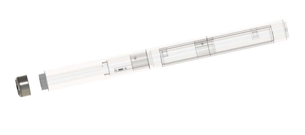
The Finished Product
Fully assembled the Tubelight looks like this:
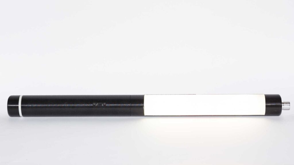
Comparing it with the original pipe light: it’s a bit shorter (about 7.5cm) and feels a lot more robust. Unsurprisingly the light output from the two variants is very similar, as they have the same LEDs, drivers and power source. And the answer to the opening question? Yes, it is better than the original – the whole thing is stronger, the tripod mount is way superior, it doesn’t look like a collection of plumbing parts and it took a lot less time to build. And having designed the parts now, putting a second one together will be even quicker.
So in conclusion, no buyer’s remorse – I’m glad I bought that 3D printer! STL files for the tubelight parts can be found here.
2 thoughts on “The Tubelight: Improving the LED Pipe Light”