Not exactly a photography related build, or at least not directly… If you want to put together your own LED lighting and you don’t happen to have a lab with a CRI testing facilities at your disposal, a spectrometer is a useful thing to have around. Whenever you want to check out those bargain LEDs you bought before you commit to building them into a light, stick them in front of it and look at the spectrum they produce If it’s not good enough, at least you haven’t wasted a lot of time and effort putting together a light that’s not up to the job. So build your own spectrometer: the build cost is very low and it’s simple to put together. So why not?
Parts
- Webcam (a fairly basic/old model is fine, as long as it works with your OS)
- Diffraction grating slide or unused DVD disk
- MDF sheet
- Paint – matt black
- Styrene sheet – black
- Cardboard – black
- Theremino Spectrometer software
… that’s it!
Webcam Preparation
The first thing to do is strip any superfluous parts off the webcam. Basically it needs to be as small as possible, so you need to get rid of any screentop mounting clip/clamp and the case. Other superfluous parts can also be removed: there’s no need for a microphone in this application, so if it has one that can go. Also any built in LED lights need to be removed, as the last thing you need is a spurious light source inside the spectrometer. Once that’s all done you should have a small circuit board with a lens on the front and a USB cable coming out of the back. The before and after for my webcam are shown below:


Depending on the webcam, there is an optional step you can take at this stage. In some webcams there’s an infra-red filter at the back of the lens assembly which can, with a bit of effort, be removed. This isn’t necessary if you’re only interested in the visible spectrum of light sources, but removing it allows you to see how much energy is being emitted as IR. This seemed like it might be interesting, so I removed the filter. On my webcam it was a square of glass fixed with a bit of glue in each corner, so I gave it a dab of isopropyl alcohol in the hope that it would soften the glue, then prised it up with a needle – it came away fairly easily without breaking.

Housing
With the webcam stripped down, the next thing to do was to build the housing. This is basically a long non-reflective tube with a slit in one end and the webcam and diffraction grating mounted at the other. When my little cylindrical webcam was stripped down it was still quite long, so to get the end of the lens more or less on the centreline it needed the tube to be 80mm across. Height-wise the webcam was pretty small, so the height of the tube wasn’t too critical.
Depending on what’s available the tube could be made from a wide range of materials: if my webcam had been shorter one of the possibilities would have been using a ‘king size’ Pringles tube. As it was, I had some MDF sheets of various thicknesses gathering dust so used them.
Based on the size of backplate needed to mount the webcam, I cut three pieces 80mm by 74mm out of 12mm MDF. Two of these had a 50mm diameter hole cut in the centre with a hole saw: these would be the anti-glare diaphragm and the front plate with the slit.
The suggestion seems to be that making the inside of the tube about 300mm long is a good plan, so for the sides I cut two pieces of 3mm MDF 325mm long and 74mm wide, and for the top and bottom two pieces 325mm long and 86mm wide. All of these were marked and drilled for fixing screws 6mm from each end and about a third of the way down their length (the recommended position for the diaphragm). Bottom and sides were then screwed to the front and diaphragm plates. At this stage the inside of the box was sprayed matt black.
Next came adding a slit to the front of the tube. For this I cut a piece of 0.5mm black styrene sheet to the size of the tube, and cut a 2mm by 25mm slit the centre. Since the styrene is slightly reflective I glued a piece of black card with a slightly bigger slit behind it to avoid internal reflections. These were then fixed to the front of the tube with the slot aligned so it was vertical.

Fitting the Webcam and Grating
With that done the fixing for the webcam had to be sorted out: it has to be aligned at an angle of 30° to the long dimension of the tube. The method for attaching the webcam will vary fairly massively depending on the type being used – helpfully some webcams appear to have a mounting hole that can be used to make life easy, but mine had nothing. However, with a bit of trigonometry to work out the angles, some black plastic angle strip with a slot cut in it and a dose of five minute epoxy I managed to get it mounted on the tube’s back plate so that it pointed in the right direction. The sides and bottom of the tube were then screwed on to the back plate.
With the webcam in place in the tube I prepared the diffraction grating. I do have a 35mm mounted slide format diffraction grating, but rather than using this I opted to use part of a (new) DVD as the diffraction material, as it was easier to mount on the lens. If you use a DVD you need to remove the silver r/w and plastic backing layers – I found the best way to do this was to make a small snip at the edge of the DVD with a pair of cutters, to loosen the layers round the cut, then use a piece of gaffer tape to pull the silver/backing layers away from the disk. When the superfluous layers had been removed I cut a square section of the disk that’s big enough to cover the lens area of the webcam with a bit to spare.
At this stage I plugged the webcam into my laptop and fired up the Theremino software to get an idea of how it was all looking. Before fixing the diffraction grating in place it’s important to get the lens focused – this is probably about the fiddliest operation in the whole build. The articles about this on the Theremino site don’t make it very clear (to my mind at least) how to do this or what to focus on, but with a bit of experimentation I came up with a technique that worked for me. With the DVD diffraction grating held in front of the lens and the spectrometer slit pointed at a CFL light bulb, I gradually focused the lens until the camera image in the Theremino display was a series of distinct bars with as little blurring as possible. (At that point the lens appears to effectively be focused on the slit.) The camera image should look something like this:

With the CFL bars as sharp as possible, the various parts of the spectrum will be projected onto the right parts of the camera’s sensor and the Theremino software will be able to do its job. Without correct focus you get some lovely oval bokeh in the image that completely confuses the software about where the bands of the spectrum are actually falling.
With the lens focused the diffraction grid could be fitted. In order to avoid light leaking directly into the lens it’s recommended to have a black tube covering the space between lens and grating. To do this I took a strip of black card and rolled it into a tube (in my case 18mm diameter and 21mm long), glueing between the layers of card with 5 minute epoxy. I then glued the tube onto the DVD section, again with 5 minute epoxy. This was then fixed onto the lens barrel, taking care that it was oriented so that it was producing a nice diffracted image (this happens when the track lines on the DVD are vertical – when they’re horizontal you get no diffraction).
Once the diffraction grating was in place I fitted the anti-glare diaphragm. This is made from a piece of 300 gsm black card with a 25mm high by 15mm wide rectangular hole cut in the centre. It fits behind the diaphragm plate with the circular hole in it, and restricts the reflected light coming through from the front of the unit.
Physically, that’s about it. Before screwing the top on to the tube I added some self-adhesive black foam sheet to various parts of the inside of the tube, as my matt black paint hadn’t dried very matt in some places.

Calibration
Calibration pretty easy. Run up the Theremino software and with the spectrometer pointing at a CFL light (and no other light in the room). The Theremino display should look something like this:
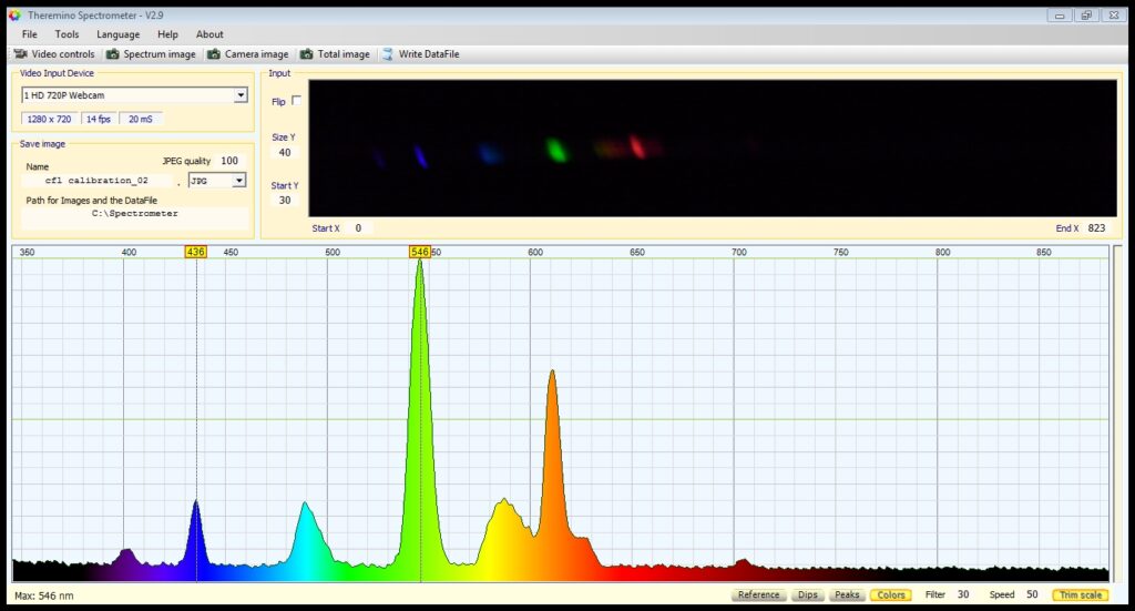
In the Theremino user interface, click the “Trim scale” button at the bottom right to give two values in yellow boxes at the top of the spectrum and zoom the spectrum window to show only the visible spectrum. Then drag the 546 line until it’s at the centre of the green spike, and the 436 line until it’s at the centre of the blue spike. Done!

Before I started playing with the LEDs this was built to measure I did a couple of other quick tests. First up a green laser:

Followed by an IR TV remote control – note, this one will only work if you have removed the IR filter from the webcam lens:

Both of those look pretty convincing! So that’s it ready for action: a spectrometer for the cost of an old webcam, a DVD and a few offcuts of MDF, all made possible by a brilliant piece of open source software from the guys at the Theremino project. It’s well worth checking out the Theremino site, as they have a ton of other interesting applications on there.

2 thoughts on “Build Your Own Spectrometer”