In the first part of this project I got to the point where I could wirelessly tether my DSLRs to the qDSLRDashboard application via a modified TP-Link MR3020 wireless router. Powering the MR3020 with a USB power bank gives a reasonably portable system, although for working in the field it’s not the slickest of setups as there are two boxes (router and power bank) rattling around needing to be secured.
So in this post I’m gong to describe how I built it all into a single hotshoe-mountable unit, so it only needs a short cable to connect to the camera’s USB port: much better for lugging around and setting up on a tripod!
Parts List
- Enclosure: 90x70x28mm plastic project box
- Battery: Samsung B500BE (ex Galaxy S4 Mini)
- Samsung battery contact block
- Li-ion charger module
- Short USB-USB mini cable (cable type will depend on your DSLR)
- Panel mount slide switch
- Hotshoe (salvaged from an old scrap flashgun)
- Vero stripboard
- M2 bolts (steel and nylon) and nylon nuts.
MR3020 Disassembly
The first step was to open up the MR3020 case. To do this I ran a knife (could have used a screwdriver or other thin metallic ‘blade’) round the top of the unit where the grey top meets the white sides. The aim here is to break the glue which the folks at the TP-Link factory are very good at applying. There’s glue most of the way round the unit, and also push clips above the power socket and diagonally across on the opposite side. Taking it slowly and working round the unit, eventually the top came free.

With the case top off, the circuit board could be removed: this was done by levering up beside the white post with a small screwdriver. The board lifted off the white posts and could be pulled back to disengage the LAN connector and switch. At this point it could be lifted out of the box. Measuring the circuit board up with a view to finding a suitable new housing for it gave dimensions of about 58mm (excluding USB connector) by 61mm (including network connector). When the router board is rehoused the USB connector needs to be accessible to connect to the camera, but there’s no need to have external access to the mode switch, LAN connector or mini USB power connector.

Battery
I was planning to use an 18650 battery to power the unit as they have plenty of capacity, but the downside is they are quite big compared with the 3020 router board, so finding a reasonable sized enclosure that fitted the battery and the router board was a challenge. Looking for an alternative I found an old Samsung Galaxy S4 Mini phone lying in a box of ‘might be useful’ junk. A quick test confirmed its battery still held its charge pretty well, so I decided to use that instead (new replacements are available if the salvaged battery isn’t up to the job). The battery is a nice slim unit but again with a decent capacity, so a much better bet for trying to fit in a box with the router.
Testing the battery with the charge circuit highlighted that getting a reliable connection to the battery’s contacts was challenging, so after an attempt at removing the spring contact block from the old phone (not a success) and weighing up the possibilities of making my own two-pin sprung contact block (not worth the effort) I bought a new Samsung replacement part on eBay for about a fiver.
So the next step was to try to get battery and contacts mounted in the base of the project box so that both are held in place and making a solid connection. Helpfully those nice Samsung people had made the pitch of their battery contacts the same as vero stripboard, so that made life a whole lot easier. The contact block was soldered onto a length of stripboard close to one end, so that when battery and contact block were in the base of the project box the ends of the box ensured a solid connection between battery and contacts.
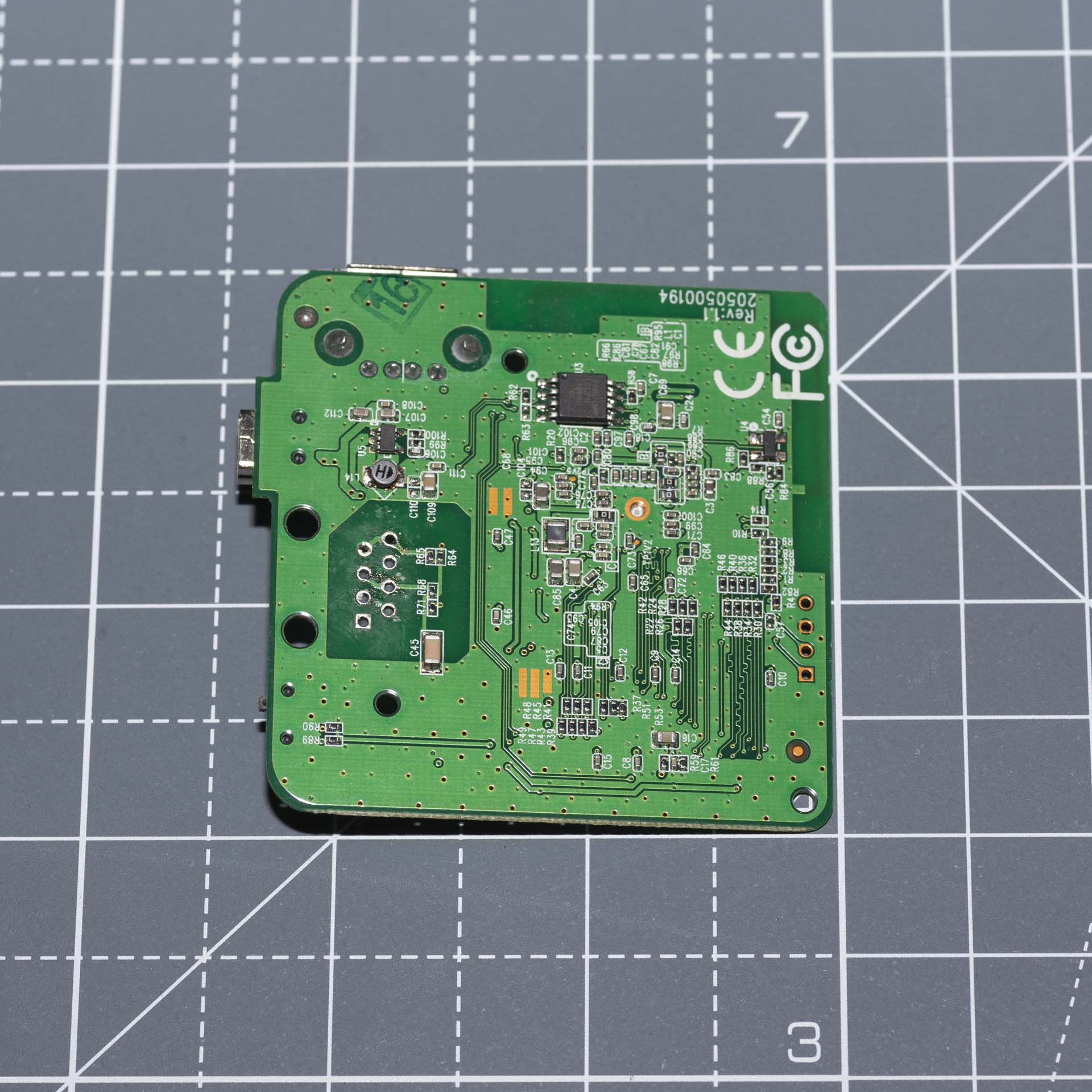
Next the router board. The biggest obstacle to fitting the board into a decent sized (i.e. not too big) project box is the LAN socket. This sticks up about 12mm from the pcb. A LAN connection is never going to be used in this application, so the socket was desoldered and removed – there are only eight pins, so it’s not difficult. Top and bottom views of the board with the LAN connector removed are shown below:

Enclosure
With the LAN socket gone it’s a bit easier to see the possibilities for fitting it in the box with battery, charging circuit and on/off switch. One of the great things about the project box I chose was that the end panels can be removed – this makes it a lot easier to see how the internals can be fitted together during planning/assembly.
I opted to mount the router board upside down in the lid of the box, as this means the USB socket is towards the back of the box on the left hand side. This is where I wanted it for a short cable connection to the USB socket on my Canon camera. Two of the box’s internal posts were removed with a Dremel so that the router board could be pushed back against the larger posts for the screws that hold the box lid. The USB socket and three board mounting hole positions were then marked and cut, and the router board was fixed into the box using three M2 bolts with small spacers to get the alignment right, and nylon nuts to avoid shorting anything on the board.

Once the router board was in place it was time to work on the charge circuit. This had a couple of status LEDs that I wanted to make visible, so the board is mounted towards the front in the bottom part of the box. A slot was cut in the side of the box just below the join between top and bottom, and with the micro-USB socket pushed into this so the end of the circuit board was flush with the inside wall of the box. Three holes were marked, drilled and tapped (M2 thread size) in the bottom of the box. All the holes in my charge circuit board were voltage terminals, so the bolts for holding the board in place needed to be nylon. A spacer was added under the positive output terminal before it was screwed into the box – the negative output terminal is over the battery, so it doesn’t have a bolt. For plugging in the micro-USB plug there’s a lot of flex in the 2mm nylon bolts, so some expoy glue was applied to the egde of the charge ciruit where it’s against the side of the box to help keep it in place.
Finally, as far as cutting holes in the box is concerned, was the on/off switch. This was mounted horizontally on the rear panel of the box, and needed a simple rectangular cutout and holes for the two mounting screws.
Assembly
Wiring it all together was just a case of taking a pair of wires from the strip board with the battery terminals to the charge circuit and the on/off switch, and another pair of wires from the other side of the switch to the router board.
The most difficult part of the wiring was getting power onto the router board. The trade-off with using such a compact box was that there wasn’t enough space to plug in a regular mini-USB plug in to the router. After getting inconclusive results trying to meter the USB power anywhere other than on the back of the mini-USB socket – which has tiny and hard to access contacts on the top of the board – I decided to cut down and hack a mini-USB plug and use that. It’s a pretty severe hack, but it seems to work OK, and with the wires bent into shape to fit behind the front panel of the box it was ‘potted’ with epoxy to keep it in shape.
The last thing to do was to add the hot-shoe foot to the bottom of the box – after looking for a new part I ended up salvaging mine from an old flash gun. I looked at a few old ‘scrappers’, but not all of them have a shoe that can be removed easily. My one was just held on by two short M2 screws, and had the bonus of a flat top to make it easy to fix on to the bottom of my project box. Fixing it in place was just a case of drilling and tapping two M2 holes in the bottom of the box. I was going to add a bit of glue for strength, but it feels solid enough without so I didn’t bother.
Assembling the unit I stuck in a couple of 2mm thick strips of styrene and some self adhesive foam under the battery to keep everything aligned, and glued the battery contact board into the bottom of the box using 5-minute epoxy. I also added a sheet of styrene above the battery to keep it in place, screwed into the internal pcb mounting posts in the bottom of the box.
Just to finish the unit off, I drilled a 2mm hole in the bottom of the box in line with the charge status LEDs on the charging module, and glued a short length of clear 2mm diameter perspex rod into it. This gives a nice red for charging, blue for charged indicator on the outside of the box.

In use the unit just has to be slid into the hotshoe and a cable connected from the camera’s USB output (mini USB on my Canons) to the USB socket on the side of the unit. Note: the shortest cable that works with my Canon DSLRs is 25cm long – the 15cm ones won’t quite reach.


I haven’t yet had the chance to see how long the slightly aged Samsung battery will power the router in the field. If the battery life isn’t great new replacements appear to be readily available and changing the battery is about five minutes’ work.