Warning: this project requires opening the body of a strobe/flash unit containing a capacitor that holds enough charge at a high enough voltage to stop your heart if you discharge it through yourself. Therefore don’t try to follow this modification unless you have enough knowledge of electrical engineering to do it safely.
There’s no doubt that a ring flash is a useful bit of equipment for getting reasonably even illumination for close up work when there’s no space for normal sized diffusers. I was looking for a small unit to use for some macro work a while back and managed to get hold of a couple of Starblitz 1000 Auto Macro-Lite units. You can find what appears to be exactly the same flash branded as Centon (MR20 Ringflash) and Vivitar (Macroflash 5000). The good news with these models is that the sync voltage appears to be safe for use with modern DSLRs, both according to this very useful resource http://www.botzilla.com/photo/strobeVolts.html, and from measuring it on my two units.
The trouble with them is that while they have both automatic and manual modes, the automatic mode is very limited and the manual mode appears to involve the unit just blasting at full power. So how can you get one of these units under control? Wouldn’t it be good to have a manual mode that allowed the power to be varied from full down to not a lot? Well, yes, and obviously it’s possible or I wouldn’t be writing this post!
Historical Precedent
Years ago before I got hold of my first strobes with variable manual power, I read an article about making a plug-in variable power controller for the legendary Vivitar 283 strobe. I’m not sure what the motivation was as Vivitar used to sell a plug-in unit (the Varipower VP1) to do exactly that.
But the idea was clever and could probably be applied to most old automatic strobes: it involved replacing the light sensor (which is just a photodiode in many cases) with a potenetiometer. By doing this instead of the current flowing through the photodiode determining the cut-off time of the flash and therefore its power, the cut-off time is determined by the current through the potentiometer, which is dependent on its resistance and is set by hand.
To make my own version of this I used an old Cobra D400 strobe. After a bit of fiddling about to get the thing apart I managed to work out what value of potentiometer to use and grafted it onto the front of the strobe. Not the most elegant piece of equipment I’ve ever made, but it worked really well as a low power and very controllable fill-in flash:
Applying this to the Starblitz
Applying the same technique to the Starblitz unit, it struck me that it would be good to put the potentiometer in the bottom section where the two AA batteries are housed, and move the batteries into a separate holder to reduce the weight on the end of the lens. To really tidy things up, the battery holder could have a hot shoe attached to the bottom. Then it could fit into the camera’s hot shoe and provide the sync connection as well …
Note that you can achieve the same type of control with a multi-position switch and a bunch of resistors instead of the potentiometer. Once you work out the correct resistor values to use this will be more repeatable and accurate than using a pot. The downside is that the switches I could find took up a lot more space so wouldn’t fit inside the strobe unit’s battery slot.
Parts List
- Battery holder – 3xAA switched
- Power plug
- Power socket
- Hot shoe sync adapter
- 2.5mm mono open jack socket
- Potentiometer – 50KΩ logarithmic
- Heat shrink sleeve
- 28 AWG multi-strand silicone wire
Modifying the Unit
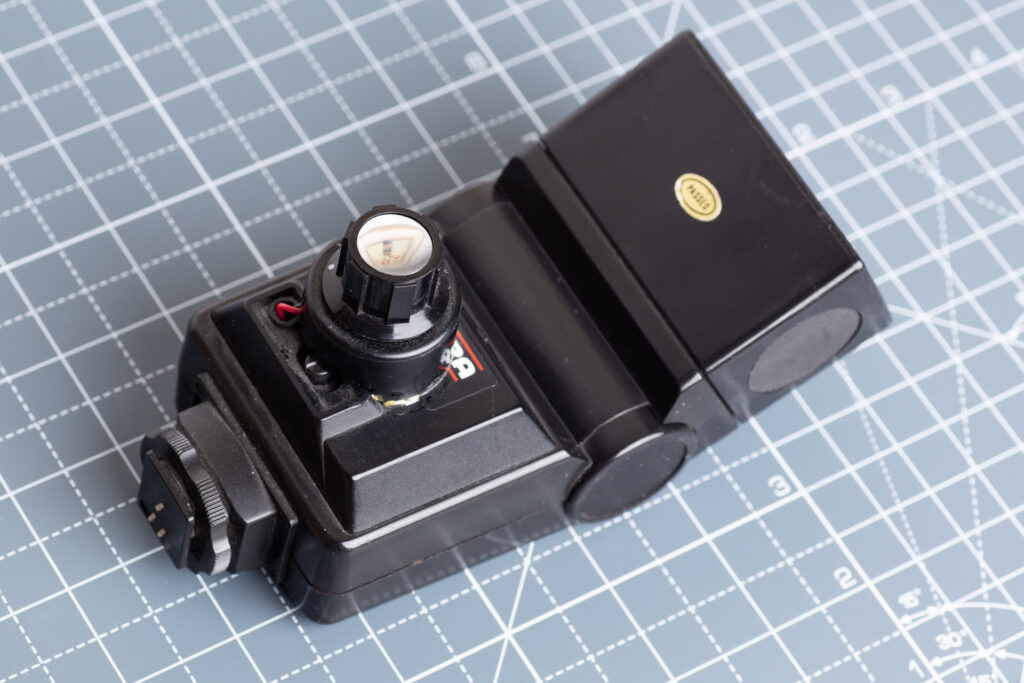
The first thing to do is to take the bottom section of the flash apart to get access to the light sensor. To do this you have to take the exposure scale off the back, exposing two screws. There’s also a small round cover on the right hand side of the flash’s back panel, which reveals a third screw. Remove these three screws and the front and back of the base part of the flash can be separated.

Beware: when the bottom part of the case opens it exposes the strobe’s main capacitor (circled above) – these things can hold enough charge to kill you, and can hold it for quite a time after the unit was last used, so be very careful! You should always ensure it is fully discharged before starting any work inside the strobe.
Strobe Mods
Once the strobe has been made safe there are two mods to make inside it:
- replace the battery contacts with a power socket, so it can be powered by the external battery pack, and
- remove the photodiode and replace it with a potentiometer of a suitable value.
Drill a hole in the strobe’s battery door and attach the power socket. Solder a pair of wires to the socket’s connectors and fix them to the wires that came off the battery terminals, making sure the polarity is correct (helpfully, the existing wires in the Starblitz unit are black and red so getting this right shouldn’t be too difficult).
Pull the photodiode out of its socket on the front body of the flash unit (circed below) – it’s just a push fit, so slides out very easily. Remove the small circuit board that’s mounted in the front section of the flash body (it’s just held by two small screws – see arrows in the photo below) and de-solder the photodiode leads, replacing them with a longer pair of wires (I use the silicone coated stuff as it is very flexible, which is useful when space is limited).

Reassembly
Replace the circuit board into the front section of the flash body and secure with the screws. I cut a hole in the bottom of the back section of the strobe’s body for the potentiometer, as since this is a two battery strobe unit, having the pot facing downwards through the bottom of the unit is the only way it was going to fit without having to add extra bodywork. Connect the two new wires to the centre and one of the end terminals of the pot.
Reassemble the flash unit, taking care not to pinch any of the new wiring. It may help to cut away a little of the internal walls of the Starblitz battery compartment to make routing the wires easier. When it’s all been tested, add a little glue to the edges of the battery terminal door so that it stays in place when you pull the power lead out of the socket.
Battery Holder Mods
At the power-pack end you just need to make a couple of mods as well. The first is to add a new power cord for the flash unit and the second is to provide the sync closure from the camera’s hot shoe.
For the power cord, remove the final contact plate that has the red wire attached to it. You don’t need the third battery since the Starblitz unit runs off 3 volts. Also remove the cover plate over the battery holder’s power switch and desolder the black wire. Now solder one core of a suitable length of twin core power cable to the recently vacated terminal of the power switch, and the second to the remaining contact plate at the end of the third battery slot (opposite end to the contact you just removed). At the other end of the cable solder on the power plug. That should be power for the flash sorted. Assuming you’ve made the mods to the flash unit by now you can give it a quick test by sticking in a couple of AA batteries, plugging it in to the flash and seeing if it powers up.
Adding Sync
Finally the sync mod. Mount a 2.5mm mono jack socket on the side of the battery holder. I used an open bodied socket, which needed a 4mm hole. An open type socket fits easily in the unused battery slot, but some of the enclosed body type sockets are longer and may not fit across the battery slot. Solder a pair of wires to the socket and run them through the battery holder to the hot shoe. How you connect to the hot shoe contacts will depend on your hot shoe adapter. Mine was metal bodied, with a sync socket on the side which a) didn’t work and b) there didn’t seem to be any way of getting it apart. To get my contacts connected I drilled and tapped a hole in the centre connector and soldered the positive wire (white in the photo below) to a washer that’s on the bolt fixed into this. The ground wire (brown) is attached to a tag on one of the three bolts that screw into the metal body of the adapter.

Time to try out the modified unit. Slide the battery unit into the camera’s hot shoe, attach the ring flash unit to the front of your macro lens, plug the power lead into the flash unit and add a 2.5mm sync cable between the battery unit and flash, then fire the shutter.

Calibration
Assuming that worked, all that’s needed is to calibrate the unit and add some marks for the key power settings round the power knob. If you’ve got a flash meter this is dead easy. If not, one of the options is to point the camera at a light wall and use the histogram to get the band of high readings in the same place as you open up the aperture. With my 50K log pot I managed to mark full, half, quarter and eighth power, with a little to spare before I hit the potentiometer’s lower end stop. That should be the unit ready to use.
In use: the photo below was taken using a mirror (hence the uncontrolled flares) with the unit on the camera. Itgive the idea though …

One thought on “Taking Control of a Cheap Macro Ring Flash”